Internal Sensors
Light sensor
The QUAD-C2 is equipped with an internal light sensor that is used to activate the setup functions when the lid is opened and to detect tamper attempts. The light sensor is sampled on a regular basis and does not have an associated measurement interval.
An alert can be generated when the lid is opened and the device detects light.
Note
A tamper alert, if enabled will be triggered by a tamper attempt or an authorised entry to change settings.
A full list of light sensor settings is given in the table at the end of the chapter.
Accelerometer
The QUAD-C2 contains an integrated 3-axis accelerometer that provides orientation and motion measurements.
The accelerometer can be used to measure:
Pitch
Roll
Tilt
Vibration Level
Impact Detection
Although these functions use the same accelerometer, they operate differently and are intended for different applications.
Tilt Measurement
The accelerometer measures acceleration in the X, Y and Z axes. Raw acceleration values are available in G and can be used for custom calculations.
To provide stable orientation measurements, each tilt measurement consists of 10 acceleration samples taken at 1 ms intervals. The average of these samples is used to calculate Pitch, Roll and Tilt.
The X axis passes through the lid of the device, the Y axis passes horizontally through the device and the Z axis passes vertically through the device.
When looking at the front cover, positive pitch is defined as the top of the QUAD-C2 tilting towards the observer. Negative pitch is defined as the top of the QUAD-C2 tilting away from the observer.
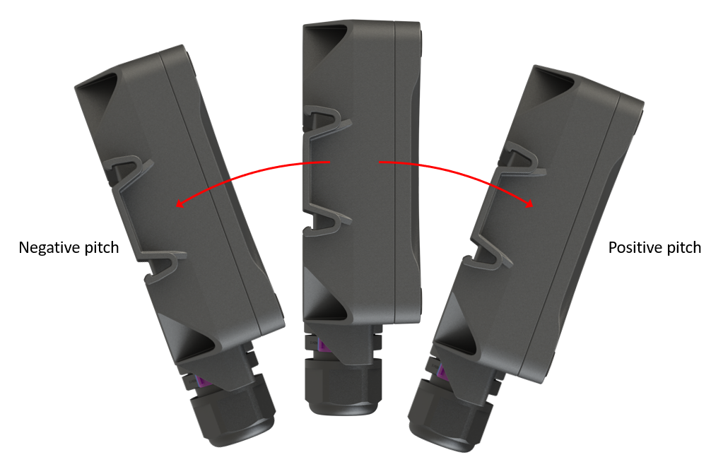
Definition of pitch
When looking at the front cover, positive roll is defined as the top of the QUAD-C2 rotating towards the right. Negative roll is defined as the top of the QUAD-C2 rotating towards the left.
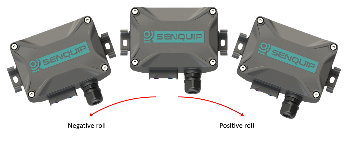
Definition of roll
Pitch and Roll are useful where the monitored object has a defined front, back, left and right, such as a vehicle. For objects such as poles or masts, Tilt is generally more useful.
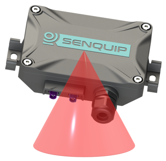
Definition of tilt
Specification
Parameter |
Specification |
|---|---|
G-force range |
+- 2G |
Resolution |
1mG |
Sensitivity change vs temperature |
0.1% per°C |
Typical zero-g level offset accuracy |
+- 40mG |
Tilt resolution |
0.1 deg |
Tilt accuracy (0-45 deg) |
1.0 deg |
Tilt accuracy (45-90 deg) |
2.0 deg |
Settings
Accelerometer measurements can be scheduled as a multiple of the base interval. Setting the Interval to 1 causes measurements to occur every base interval. Increasing the interval reduces power consumption.
Pitch, Roll and Tilt warning and alarm thresholds can be configured. After each measurement, the measured value is compared with the configured warning and alarm limits. If a threshold is exceeded, an alert message is transmitted immediately. While the condition persists, messages are transmitted at the exception interval.
Hysteresis can be configured to prevent repeated alerts when measurements fluctuate around a threshold due to vibration.
Note
Pitch and Roll warning and alarm levels may be positive or negative. Tilt warning and alarm levels are always positive.
Vibration Level
The reported Vibration Level provides an indication of the amount of vibration present during the measurement interval. It is intended for long-term condition monitoring, such as detecting increasing vibration caused by bearing wear, imbalance or mechanical deterioration.
Each time a vibration measurement is performed:
The latest 32 acceleration samples are read from the accelerometer.
A statistical variance calculation is performed on the X, Y and Z measurements.
The calculated Vibration Level is reported.
Because only the most recent 32 samples are analysed, the reported Vibration Level represents the vibration at the time the measurement was taken. A short impact that occurs between measurements may not be reflected in the reported value.
Vibration Level is therefore best suited to measuring changes in vibration over time rather than detecting individual impact events.
Impact Detection
Impact Detection is designed specifically to detect short-duration shock events.
Unlike Vibration Level, the accelerometer continuously monitors acceleration in hardware. Two independent impact detectors are available, each with its own configurable acceleration threshold and minimum duration.
Each impact detector has its own acceleration threshold and minimum duration. When both conditions are satisfied, the accelerometer immediately generates an interrupt. The device records the event and can transmit an Impact alert.
Because monitoring is continuous, impacts are detected regardless of when they occur within the base interval.
Note
An Impact alert indicates only that the configured threshold has been exceeded. It does not report the actual peak acceleration. For example, if an impact threshold is configured for 200 mG and an alert is generated, the actual impact may have been 210 mG, 500 mG or higher.
The two impact detectors allow different severity levels to be configured independently. For example:
Impact 1: 200 mG for 30 ms
Impact 2: 400 mG for 200 ms
Choosing the Correct Measurement
Requirement |
Recommended Feature |
|---|---|
Measure orientation |
Pitch, Roll or Tilt |
Monitor machine vibration |
Vibration Level |
Detect long-term vibration trends |
Vibration Level |
Detect shock or impact events |
Impact Detection |
Note
Vibration Level and Impact Detection are independent functions. It is therefore normal for an Impact alert to be generated while the reported Vibration Level remains relatively low.
Pressure sensor
The QUAD-C2 contains provision for a built-in pressure sensor for measuring atmospheric pressure and short term height change. Although the enclosure is rated to IP67, an integrated moisture resistant gore-vent allows internal and external pressure to equalise, meaning accurate atmospheric pressure can be measured.
Note
The pressure sensor is not fitted by default, contact Senquip for ordering options.
Specification
Parameter |
Specification |
|---|---|
Pressure range |
300 - 1100 hPa |
Temperature range |
-40 to 85°C |
Absolute accuracy (0 to 65 deg C) |
+-1hPa |
Relative accuracy (25 to 40 deg C) |
+-0.12hPa, equivalent to +-1m altitude |
Absolute maximum pressure |
20,000hPa |
Settings
Measurements can be scheduled as a multiple of the base-interval. The fastest possible measurement rate is achieved by setting the interval to 1 in which case measurements will occur on every base interval. To reduce power consumption, the measurement rate can be turned down by increasing the interval.
Warning and alarm thresholds for pressure can be enabled. Once enabled, each time a measurement is completed, the returned value will be compared with minimum and maximum warning and alarm thresholds. If a warning or alarm level is breached, a message will immediately be transmitted. As long as the warning or alarm condition persists, messages will be transmitted at the exception-interval rather than the transmit-interval. Hysteresis can be specified in 1 kPa increments, to prevent multiple alarms in the presence of fluctuating pressure, for instance due to wind.
A full list of pressure sensor settings is given in the table at the end of the chapter.
Magnetic switch
The QUAD-C2 contains a built-in hall-effect sensor that acts as a magnetic switch. When the switch detects a magnet, the QUAD-C2 can be made to enter setup mode, wakeup, or trigger a function in a script.
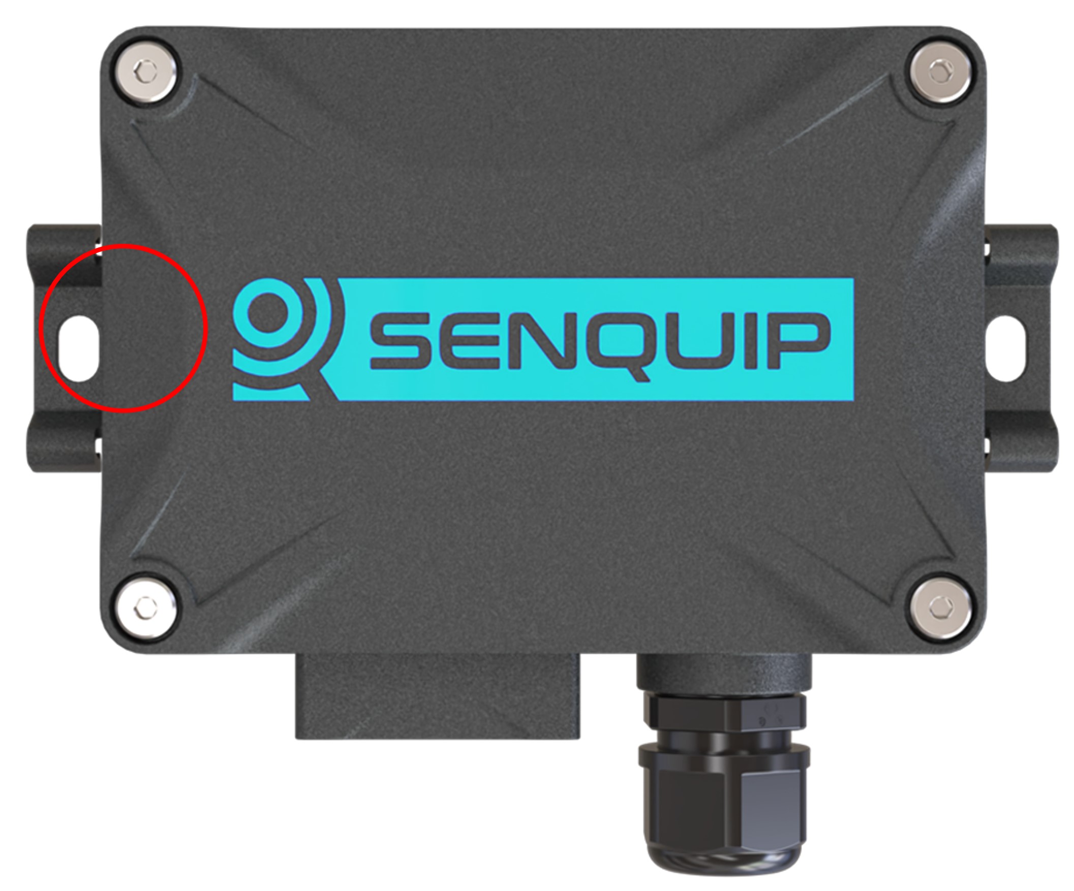
Location of magnetic switch
Settings
Three actions are available when the magnetic switch is activated.
Setup: Put the device into setup mode. Identical to pressing the Setup button. If the device is asleep, it will wake and enter Setup Mode.
Wake: Wake the device up and perform a measurement cycle. There is no action if device is already awake.
Trigger: Wake the device if asleep. Trigger TP0 before first measurement cycle. TP0 should be handled in a script.
Temperature sensor
An integrated temperature sensor allows for measurement of ambient temperature. Please be aware that the temperature sensor will measure the temperature inside the QUAD-C2 enclosure; this temperature can be subject to fluctuations, for example when the internal battery is charging and so the environment within the device heats up. For accurate external temperature measurement or to measure a wider range of temperatures, use an external temperature sensor.
Specification
Parameter |
Specification |
|---|---|
Measurement range |
-40 - 85°C |
Resolution |
0.01 deg°C |
Absolute accuracy (25°C) |
+-0.5 deg°C |
Absolute accuracy (0 - 65°C) |
+-1 deg°C |
Settings
Measurements can be scheduled as a multiple of the base-interval. The fastest possible measurement rate is achieved by setting the interval to 1 in which case measurements will occur on every base interval. To reduce power consumption, the measurement rate can be turned down by increasing the interval.
Warning and alarm thresholds for ambient temperature can be enabled. Once enabled, each time a measurement is completed, the returned value will be compared with minimum and maximum warning and alarm thresholds. If a warning or alarm level is breached, a message will immediately be transmitted. As long as the warning or alarm condition persists, messages will be transmitted at the exception-interval rather than the transmit-interval. Hysteresis can be specified in 1°C increments, to prevent multiple alarms in the presence of fluctuating temperature.
A full list of temperature sensor settings is given in the table at the end of the chapter.
GPS
Models of the QUAD-C2 that have 4G LTE connectivity also have an integrated Global Navigation Satellite System (GNSS). The GNSS receiver, allows for position and speed based reporting. The internal GNSS received uses GPS, GLONASS, BeiDou and Galileo satellites to ensure high accuracy measurement and fast time to first fix. Data available from the GPS includes:
Latitude, longitude and altitude
Speed (km/h) and bearing
Date and time
Number satellites being tracked
In order to utilise GNSS, the antenna needs to be mounted with clear visibility of the sky. Plastic and fibreglass roof sheeting will have a minimal effect on GNSS performance whereas reinforced concrete and metal roofs will render the GNSS inoperable. Good GNSS signal quality will result in quicker time to position acquisition and lower power use.
Specification
Parameter |
Specification |
|---|---|
Time to first fix from power up |
Typically 60 seconds |
Position update rate |
Maximum 1Hz |
Horizontal position accuracy |
Typically +/-5m (<2.5m CEP) |
Vertical position accuracy |
Typically +/-20m |
Horizontal speed accuracy |
1km/h |
GPS/Galileo L1 |
1575.42MHz |
GLONASS L1 |
1602.5625MHz |
BeiDou |
1561.098MHz |
Note
GNSS accuracy is specified as Circular Error Probable (CEP). A specification of <2.5m CEP indicates that 50% of position fixes will be within 2.5m of the true position. Typical 95% accuracy is better than 5m under open-sky conditions.
Settings
Measurements can be scheduled as a multiple of the base-interval. The fastest possible measurement rate is achieved by setting the interval to 1 in which case measurements will occur on every base interval. To reduce power consumption, the measurement rate can be turned down by increasing the interval. The GNSS is a high power peripheral and so use should be limited when running on battery power.

GPS alert parameters
The GNSS can create an alert based on position and speed. A known position (expected latitude and expected longitude) can be specified and if the device moves a particular radius from that point, an alert can be raised. Hysteresis can be specified in 1 meter increments to prevent multiple alerts, for instance as a boat swings on a mooring near the edge of the allowed radius. Likewise, a maximum speed can be specified and if the device exceeds that speed, an alert will also be raised. Speed hysteresis can be specified in 1km/h increments, to prevent multiple alerts as the speed fluctuates at the alert point. The time that GNSS speed exceeds 2km/h can be counted and used to calculate machine utilisation.
Note
In the example above, the QUAD-C2 could also report bilge water level, solar battery voltage and a host of other parameters associated with the yacht.
A full list of GNSS settings is given in the table at the end of the chapter.
Bluetooth interface
The QUAD-C2 has a Bluetooth peripheral that can transmit and receive Bluetooth Low Energy (BLE) advertising packets. BLE beacons typically use the advertising packets to communicate measured data such as temperatures, voltages, movement, and battery voltage. BLE tags are a special type of beacon that typically only contain identification information and are used to locate items. BLE beacons send advertising messages at different rates. Some report every second and some may be every minute or more. Battery operated BLE devices tend to send at lower rates to save power. Some BLE device are smart and will slow their send rate if they are not being used. A tire pressure monitoring device may stop sending if the tire is not rotating. Typical protocols used in advertising packets include Eddystone and iBeacon. The QUAD-C2 supports both.
The BLE beacons from ELA shown below enable identification, and measurement of temperature, humidity, voltage, switch position, and more.
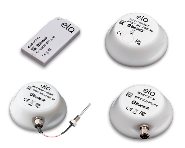
Example BLE beacons from ELA
The QUAD-C2 will report the beacon address, data, and the strength of the received signal.
The address (or identifier) is unique and allows individual tags to be recognised.
The data may contain battery voltage, temperature, humidity, or any other data being conveyed by the beacon.
The receive signal strength (RSSI) gives an indication of how strong the signal from the beacon is.
For details on using the QUAD-C2 as a BLE beacon to transmit custom advertising packets, please refer to the Senquip Scripting Guide.
Note
The BLE module and Wi-Fi module share a common radio. BLE operation will work best when the QUAD-C2 is operated using a cellular network rather than Wi-Fi.
Specification
Parameter |
Specification |
|---|---|
Bluetooth version |
4.2 |
Settings
Measurements can be scheduled as a multiple of the base-interval. The fastest possible measurement rate is achieved by setting the interval to 1 in which case the Bluetooth peripheral will be sampled on every base interval. To reduce power consumption, the measurement rate can be turned down by increasing the interval.
When active, the Bluetooth peripheral will scan for all advertising packets. In a typical environment, phones, computers, and other devices are all advertising. The QUAD-C2 Bluetooth peripheral could easily report a dozen Bluetooth devices even when the one you are searching for is off. A filter allows only the required Bluetooth devices to be reported by filling in the Address Capture List. Required addresses should be entered in hexadecimal and should be separated by commas. When the QUAD-C2 wakes for the next measurement interval, the Bluetooth peripheral will be sampled until all the messages listed have been found or the Capture Time has been reached. If multiple messages with the same identifier are required in a single measurement interval, place a * followed by the number of messages of that identifier to be returned after the identifier in the list. For example: 98588A10375E*4, 98588a103777, 98588a103888*10 will return 98588A10375E four times, 98588a103777 once and 98588a103888 ten times. Leave the ID Capture List blank to receive all messages.
The Capture Time setting can be used to set a timeout after which the Bluetooth peripheral will stop listening, allowing the device to transmit received messages and return to sleep. Capture-time can be used as a mechanism to allow the QUAD-C2 to sample the environment for devices for a defined time-period.
A full list of Bluetooth settings is given in the table at the end of this chapter.
Warnings and Alarms
For each measurement type, high and low warning and alarm levels can be set. Once enabled, each time a measurement is completed, the returned value will be compared with low and high warning and alarm thresholds. If a warning or alarm level is breached, a message will immediately be transmitted. As long as the warning or alarm condition persists, messages will be transmitted at the exception-interval rather than the transmit-interval.
Note
If calibration has been applied, then the warning and alarm thresholds should be set in the calibrated units.
To set a high level warning or alarm level only, set the low level to a value that is impossible to achieve. For instance to set a high only warning at 50V, set the low warning to -1V which is an unachievable value.
Hysteresis
Hysteresis prevents repeated alarms when a measured value fluctuates near a threshold. The hysteresis value is applied on both sides of the configured threshold. For an upper alarm, the value must reach upper threshold + hysteresis to enter the alarm state, then fall to upper threshold - hysteresis to clear it. For a lower alarm, the value must fall to lower threshold - hysteresis to enter the alarm state, then rise to lower threshold + hysteresis to clear it. Between the two switching points, the alarm retains its current state. Hysteresis uses the measurement configured units.
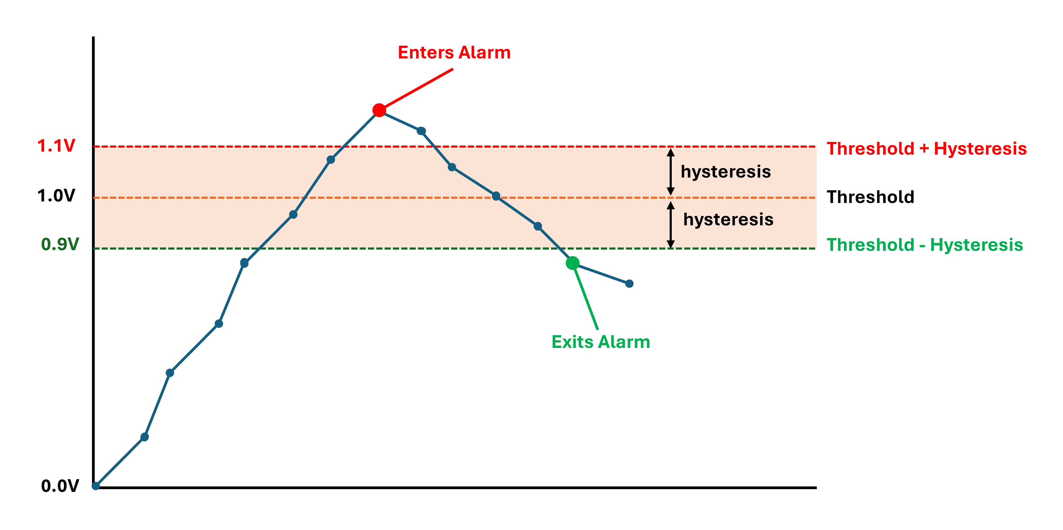
Upper alarm with a 1.0 V threshold and 0.1 V hysteresis. The alarm starts when the measured value reaches 1.1 V and clears when it falls to 0.9 V. Between those values, the alarm retains its current state.
Internal sensor settings
A full list of settings for internal sensors is given in the table below.
Name |
Item |
Function |
Range |
Unit |
Internal Reference |
|---|---|---|---|---|---|
Light Sensor |
|||||
Name |
text |
A name for the light sensor that is meaningful to the user. |
25 chars |
tamper.name |
|
Tamper Alert |
boolean |
This parameter determines if an alert is generated when the light sensor detects light or not. |
tamper.enable |
||
Ambient Temperature |
|||||
Name |
text |
A name for the input that is meaningful to the user. |
25 chars |
ambient.name |
|
Interval |
integer |
The number of base intervals after which the temperature is sampled. A value of 1 means that the input is collected every base interval. Set to 0 to disable. |
0 to 10000 |
ambient.interval |
|
Hysteresis |
decimal |
The amount by which the measured value has to drop below the threshold to re-enable the alert after an event. |
0 to 100 |
°C |
ambient.hysteresis |
Warning |
text |
Warning thresholds. Refer to user guide. |
-40 to 100 |
°C |
ambient.warning |
Alarm |
text |
Alarm thresholds. Refer to user guide. |
-40 to 100 |
°C |
ambient.alarm |
Accelerometer |
|||||
Name |
text |
A name for the input that is meaningful to the user. |
25 chars |
accel.name |
|
Interval |
integer |
The number of base intervals after which the accelerometer is sampled. A value of 1 means that the input is collected every base interval. Set to 0 to disable. |
0 to 10000 |
accel.interval |
|
Output XYZ Vectors |
boolean |
Send X,Y,Z gravity vectors in data output. |
accel.outputxyz |
||
Hysteresis |
decimal |
The amount by which the pitch, roll or angle has to exceed a threshold before triggering alarms or warnings. |
0 to 20 |
Degrees |
accel.hysteresis |
Pitch Warning |
text |
Warning thresholds. Refer to user guide. |
-90 to 90 |
Degrees |
accel.pitch.warning |
Pitch Alarm |
text |
Alarm thresholds. Refer to user guide. |
-90 to 90 |
Degrees |
accel.pitch.alarm |
Roll Warning |
text |
Warning thresholds. Refer to user guide. |
-90 to 90 |
Degrees |
accel.roll.warning |
Roll Alarm |
text |
Alarm thresholds. Refer to user guide. |
-90 to 90 |
Degrees |
accel.roll.alarm |
Angle Warning |
text |
Warning thresholds. Refer to user guide. |
0 to 90 |
Degrees |
accel.angle.warning |
Angle Alarm |
text |
Alarm thresholds. Refer to user guide. |
0 to 90 |
Degrees |
accel.angle.alarm |
Motion Warning |
text |
Warning thresholds. Refer to user guide. |
0 to 5000 |
milli-g |
accel.motion.warning |
Motion Alarm |
text |
Alarm thresholds. Refer to user guide. |
0 to 5000 |
milli-g |
accel.motion.alarm |
Wake from Hibernate |
boolean |
The high warning motion threshold is used to wake the device when hibernating. |
accel.motion.wake_from_hibernate |
||
Motion Wake Threshold |
decimal |
The motion threshold above which the device will wake from hibernation. |
1 to 2000 |
milli-g |
accel.motion.wake_threshold |
Count Motion Hours |
boolean |
Counts the number of hours the device exceeds the Motion Wake Threshold. Typically used as an machinery work vs idle hour meter. |
accel.motion.count_hours |
||
GPS |
|||||
Name |
text |
A name for the GPS signal that is meaningful to the user. |
25 chars |
gps.name |
|
Interval |
integer |
The number of base intervals after which the gps is sampled. A value of 1 means that the input is collected every base interval. Set to 0 to disable. |
0 to 10000 |
gps.interval |
|
Max Time |
integer |
Maximum time the device will wait for a valid GPS fix. |
0 to 3600 |
Seconds |
gps.maxtime |
Position |
|||||
Position Alert |
boolean |
Sets whether a change in position generates an alert. |
gps.position.alert.enable |
||
Radius |
integer |
An alert will be raised if the device moves further than this value from the expected position. |
1 to 10000 |
Meters |
gps.position.alert.radius |
Hysteresis |
integer |
Once the alert is active or inactive, the radius must change by this value to change the alert state. |
1 to 10000 |
Meters |
gps.position.alert.hysteresis |
Expected Latitude |
decimal |
Latitude at which the device is expected to be. |
-90 to 90 |
Degrees |
gps.position.alert.lat |
Expected Longitude |
decimal |
Longitude at which the device is expected to be. |
-180 to 180 |
Degrees |
gps.position.alert.lon |
Speed |
|||||
Count Movement Hours |
boolean |
Counts the number of hours the device is moving according to the GPS speed. |
gps.speed.count_hours |
||
Speed Alert |
boolean |
Sets whether a change in speed generates an alert. |
gps.speed.alert.enable |
||
Threshold |
integer |
An alert will be raised if the device’s speed goes above this threshold. |
1 to 1000 |
km/h |
gps.speed.alert.threshold |
Hysteresis |
integer |
Once the alert is active or inactive, the speed must change by this value to change the alert state. |
1 to 1000 |
km/h |
gps.speed.alert.hysteresis |
Bluetooth |
|||||
Name |
text |
A name that is meaningful to the user. |
25 chars |
ble.name |
|
Interval |
integer |
The number of base intervals after which the Bluetooth module is turned on. Set to 0 to disable. |
0 to 10000 |
ble.interval |
|
Scan Time |
integer |
The device will capture matching messages for this length of time. |
Seconds |
ble.capture_time |
|
Address Capture List |
text |
List of adresses to be captured in HEX format, separated by a comma. Leave blank to capture all. |
200 chars |
ble.id_list |
|
Send Raw Data |
boolean |
If ticked, all captured messages will be added to the data message. |