Installation
Opening the Box
The ORB-C3 is shipped in a box with a security seal that ensures that the packaging has not been opened. If this seal is compromised, the box may have been opened, in which case, a non-authorised party could have had access to the device password. If the device is to be used in a critical application, please ensure that the seal is intact upon receipt and remember to change your password as soon as possible.

ORB-C3 packaging with intact security seal
Mounting
The ORB can be mounted directly on a flat surface or can be attached to a pole or wall using the appropriate mounts that are included when you purchase your ORB.
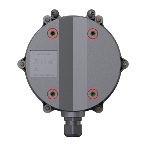
ORB mounting points circled in red
When attaching the ORB to a panel, use the four M5 bolts that are included and screw directly into the tapped holes on the rear of the ORB enclosure.
Warning
The depth of the tapped holes in the rear of the ORB enclosure is limited to 5mm; attempting to fasten to a depth exceeding 5mm may damage the enclosure.
Two multipurpose brackets that allow mounting to a pole or a wall are included with your ORB.
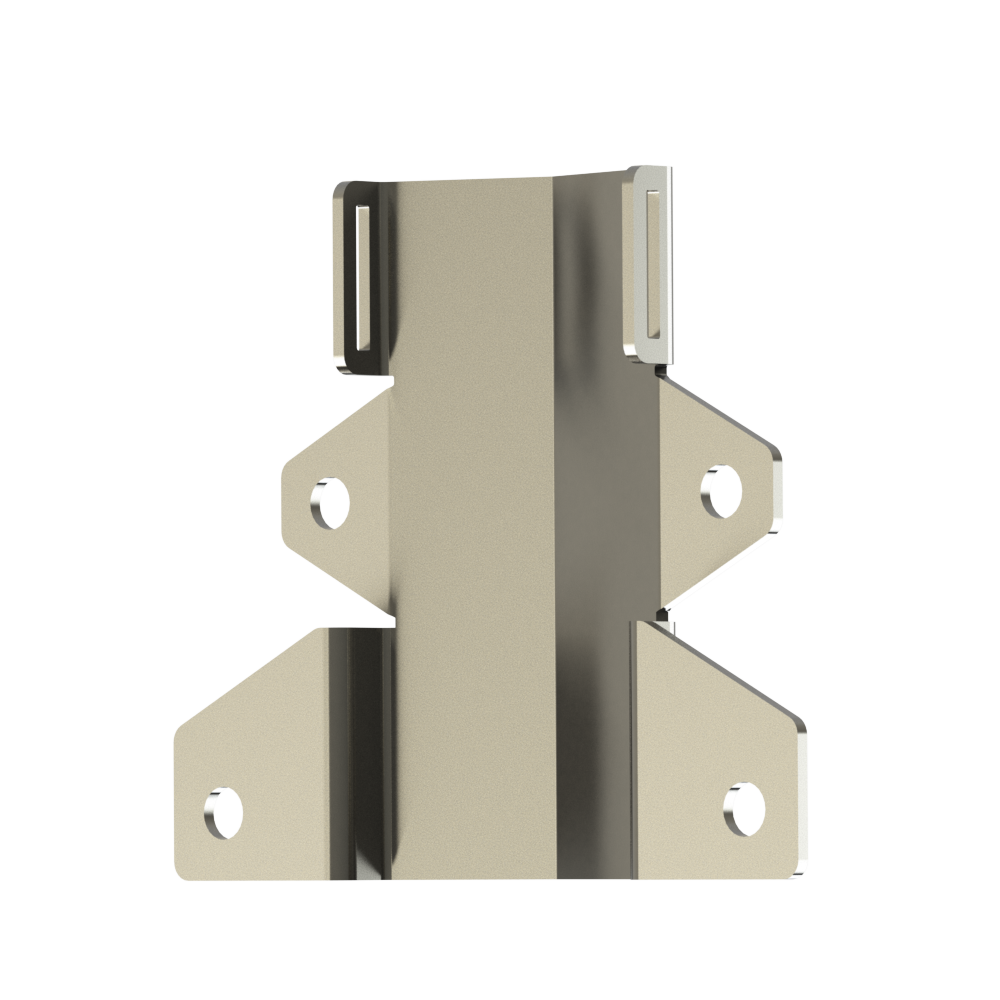
ORB mounting brackets
If attaching to a pole, use the four M5 bolts provided to attach the brackets as shown below. The pole mounting plate is designed to be used with commonly available jubilee-clips. Thread the strap end of a jubilee-clip through the slots in the top of the bracket. Repeat for the bottom bracket with a second jubilee-clip. Pass the straps around the pole and into the clamps. Tighten to secure the ORB to the pole.
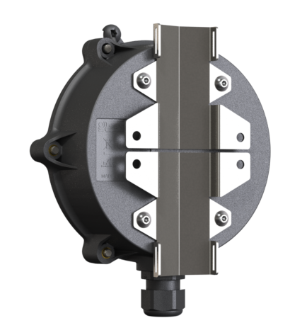
Attaching the pole mount bracket
The same mounting brackets can be used to attached the ORB to a wall. Attach the brackets to the rear of the ORB as shown below using the four supplied M5 bolts; note that the brackets are rotated 180 degrees when compared with how they are used for pole mounting.
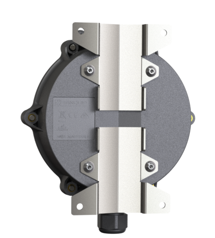
Attaching the wall mount bracket
Note
Jubilee-clips and wall mounting bolts are application specific and are not provided as part of the ORB kit.
The ORB should be mounted with the cable entry gland facing the ground. Mounting the ORB with the gland in another orientation may result in water ingress via the cable entry gland. The ORB contains GPS, Wi-Fi and 4G LTE4 antennas that may not function optimally if the monitor is mounted in the incorrect orientation. In-field orientation checks can be performed using the built-in accelerometer and associated tilt measurements.
User Access
The user access panel is accessed by removing the hinged front cover. From the user access panel, batteries can be replaced, a SIM card can be inserted, wiring functions can be performed, diagnostics can be performed and the device can be reset or placed in setup mode.
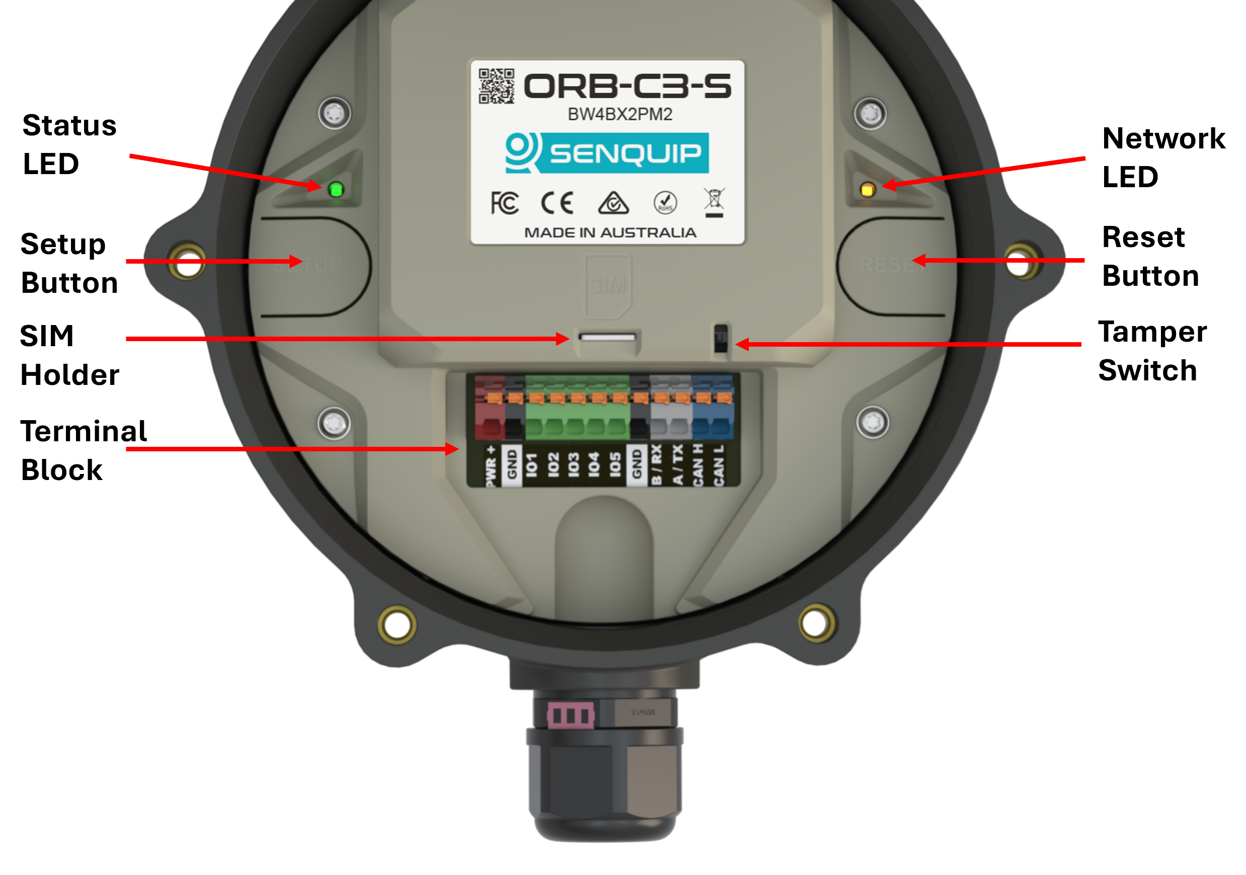
ORB-C3 user access
To open the cover:
Un-fasten the 6 hex-head screws that secure the cover using the 3mm Allen key provided. The screws are captive and will not fall out when loose. Do not attempt to remove the screws from the lid.
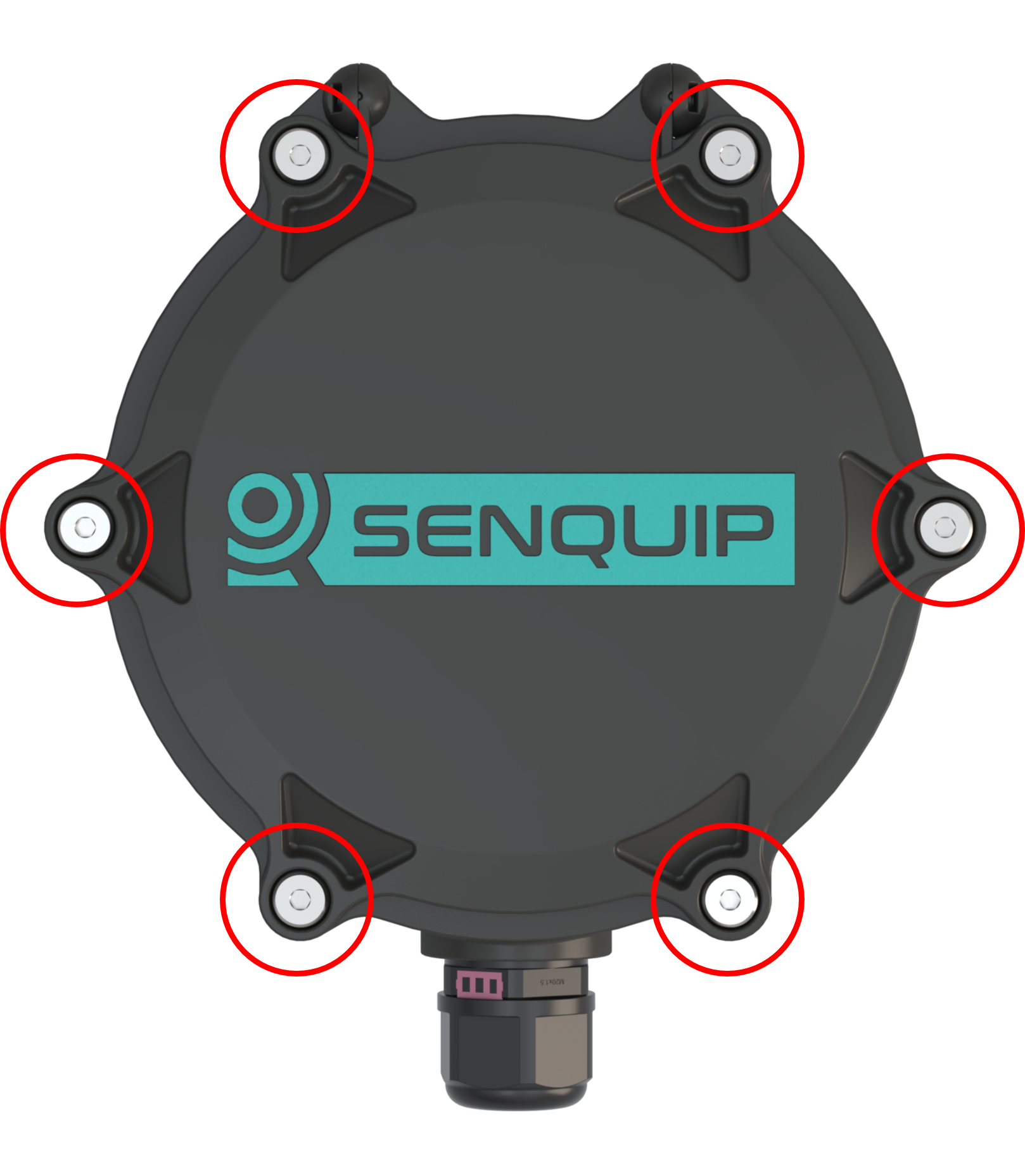
Six captive cover screws
Open the hinged lid by lifting the bottom of the lid toward yourself and up.
Note
A mechanical tamper switch will detect the lid opening and, if enabled, will dispatch an alert.
Note
When closing the ORB, please ensure that the seal is correctly seated and is clean. A poorly seated or dirty seal may result in water ingress.
Anti Tamper Screw
In some installations, evidence needs to be provided where unauthorised access to the Senquip ORB-C3 has occurred. All devices include a tamper feature that can be configured to raise an alert when the lid is opened. In some instances however, a physical tamper indication is required. Senquip can provide tamper evident screws for the lid of the Senquip ORB-C3. Once a tamper evident screw is in place, opening the device will require breaking the seal on the tamper evident screw.
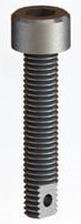
Tamper evident screw
To fit a tamper evident screw, remove one of the lid screws closest to the cable gland using the 3mm Allen key provided. Replace the lid screw with the tamper evident version. The tamper screw is compatible with most available seals.
Note
The tamper evident screw should be inserted last and removed first. The tamper evident screw should be inserted and removed with a 4mm Allen key.
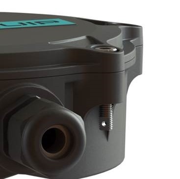
Tamper evident screw in place on ORB-C3
SIM Card Installation
The ORB-C3 supports three SIM options:
SoftSIM - A software SIM that requires no additional hardware. SoftSIM availability depends on network support and service availability. SoftSIMs offer high reliability and simplified deployment. Contact Senquip for more information.
eSIM - Provision is made on the PCB for a customer-supplied MFF2 eSIM component. eSIMs provide excellent reliability in high-vibration environments. Contact Senquip for more information.
Nano-SIM - A Nano-SIM holder is provided for customers wishing to use their own SIM cards. Nano-SIMs offer the greatest flexibility and network choice.
If mobile communications are required and a SoftSIM or eSIM is not fitted, a Nano-SIM card must be installed. The ORB-C3 supports both 1.8V and 3.3V Nano-SIM cards.
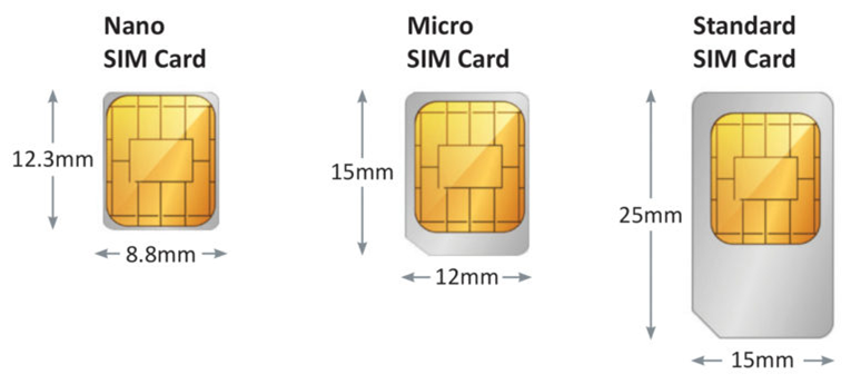
SIM card sizes
Note
If your ORB-C3 is fitted with a SoftSIM or eSIM, a Nano-SIM card is not required.
To access the Nano-SIM holder, open the enclosure lid. The SIM holder is a push-push type. Push the SIM card fully into the holder to install it. To remove the SIM card, push it gently and release. The SIM card will eject from the holder.
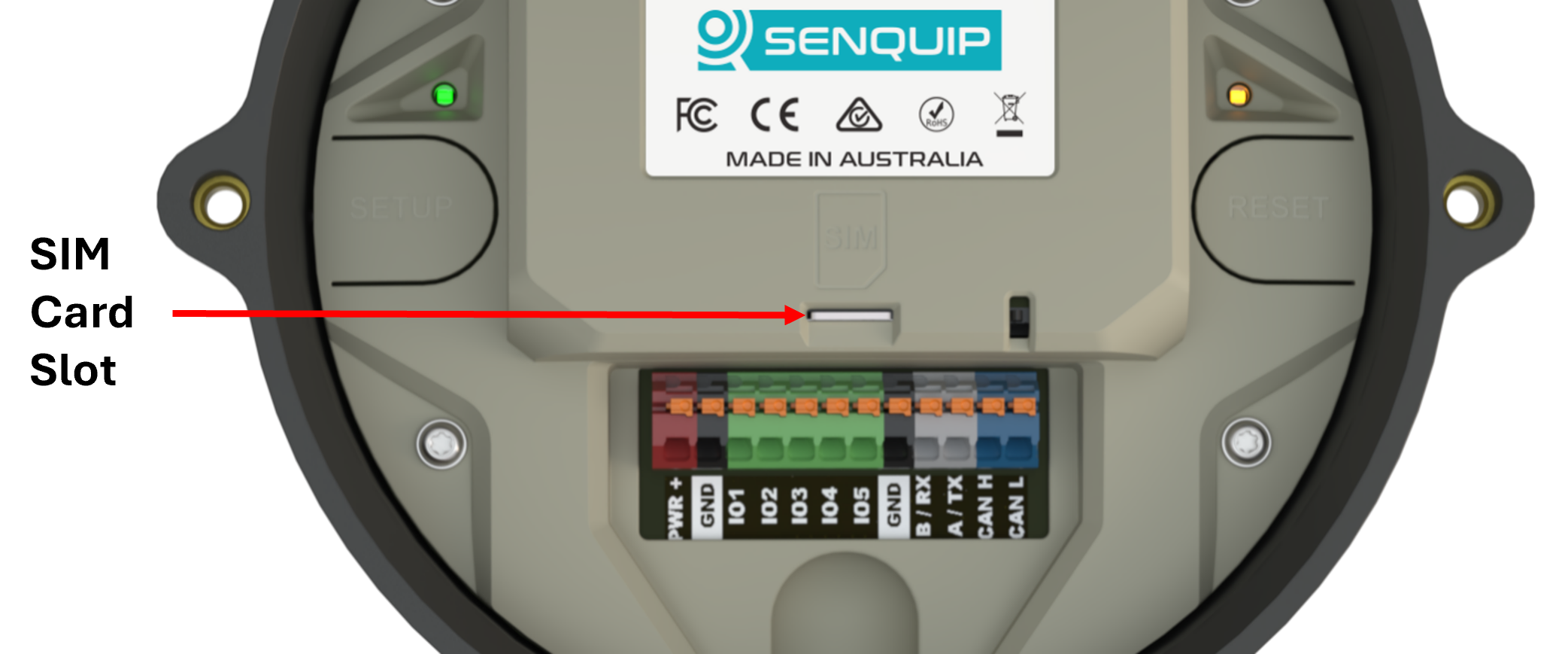
Identifying the SIM card slot
To install a Nano-SIM card, orient it with the chamfered corner in the bottom-right position and push it fully into the SIM holder until it clicks into place.
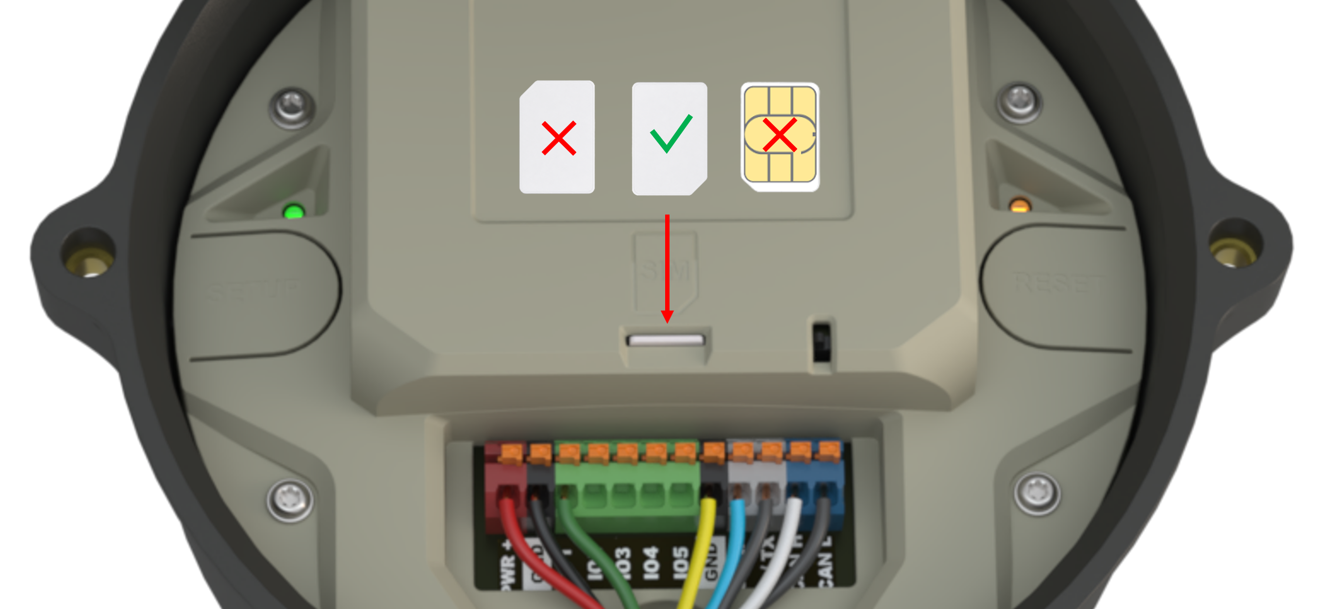
Correct orientation of a Nano-SIM card
The enclosure lid incorporates a retention feature that helps secure the SIM card in harsh operating environments. Ensure the enclosure is fully closed and secured after installing the SIM card.
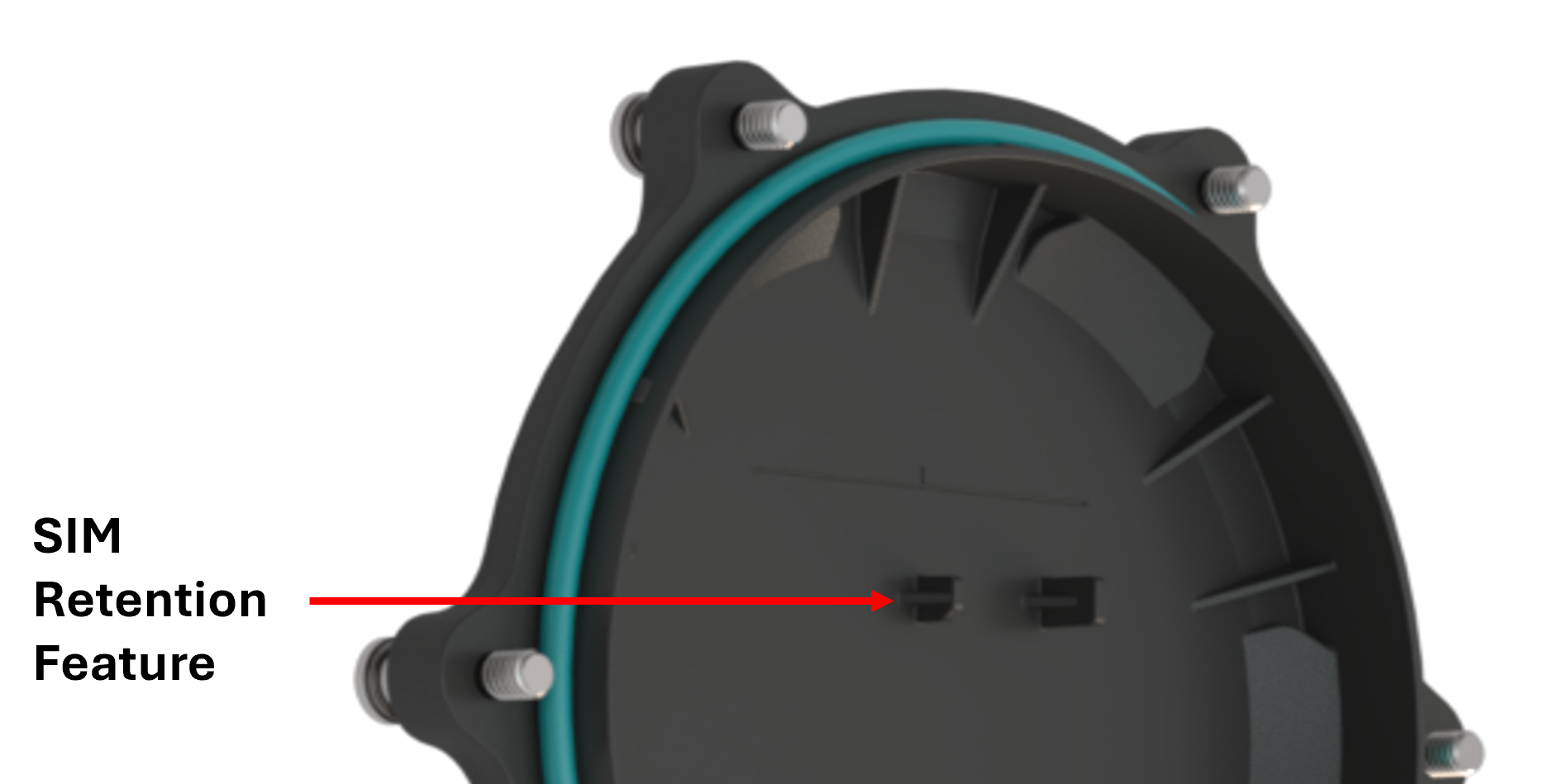
SIM card retention feature
After installing or removing a SIM card, it is recommended that the ORB-C3 be reset so that the modem can detect the change.
Wiring Guide
The Senquip ORB-C3 is fitted with a 12 way 3.5mm colour coded pitch terminal block that can be used to provide power and for connection to external sensors and systems. With the cable gland facing down, pin 1 is on the left hand side of the header and pin 12 on the right. All references to pin numbers in this document will assume this definition.
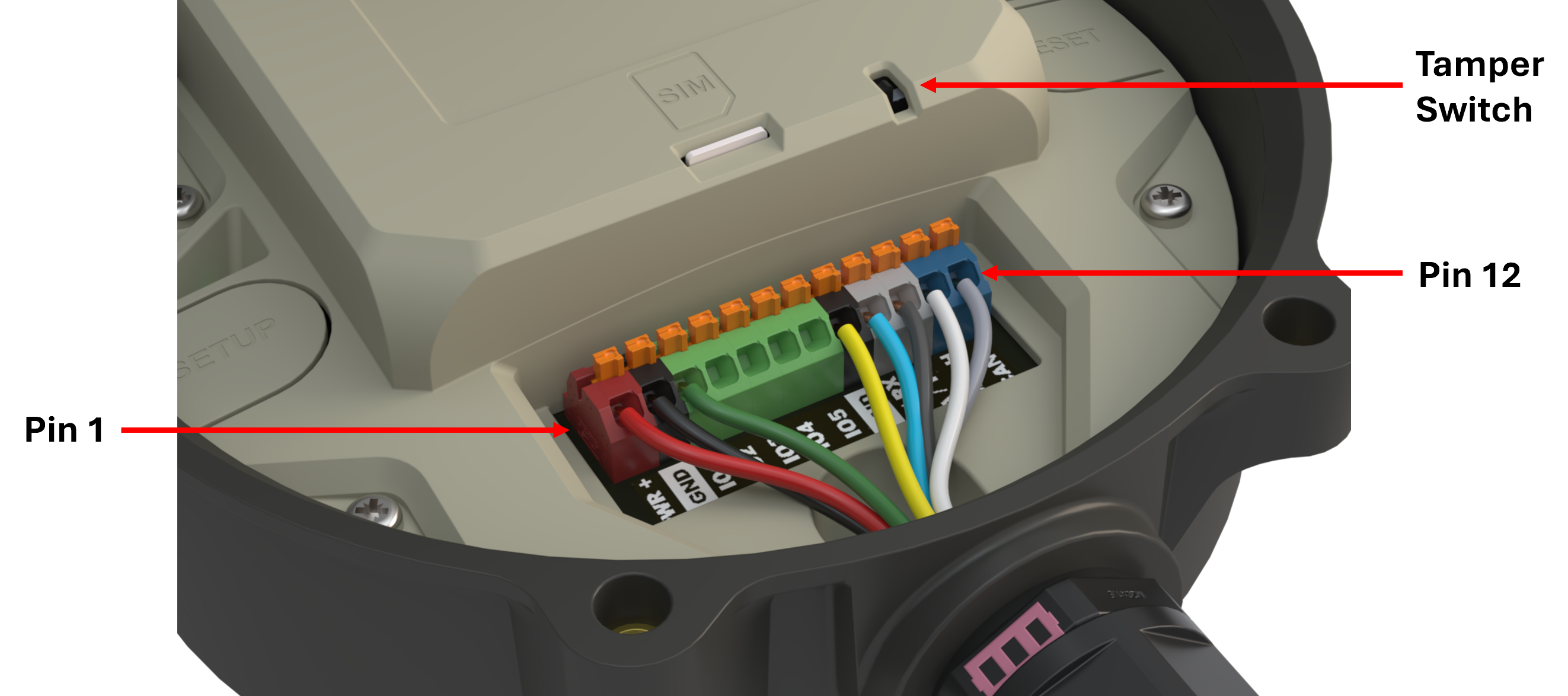
ORB-C3 terminal block detail
The following pinout applies to the 12 way terminal block:
Pin number |
Name |
Terminal block marking |
Application |
|---|---|---|---|
1 |
Positive voltage in |
PWR+ |
Positive system power; either permanent or intermittent such as from a solar panel |
2 |
Negative voltage in (ground) |
GND |
Negative system power or ground |
3 |
General purpose input output 1 |
IO1 |
Voltage, current, frequency, pulse input and sink or source output |
4 |
General purpose input output 2 |
IO2 |
Voltage, current, frequency, pulse input and sink or source output |
5 |
General purpose input output 3 |
IO3 |
Voltage, current, frequency, pulse input and sink or source output |
6 |
General purpose input output 4 |
IO4 |
Voltage, current, frequency, pulse input and sink or source output |
7 |
General purpose input output 5 |
IO5 |
Voltage, current, frequency, pulse input and sink or source output |
8 |
Ground |
GND |
Spare ground for sensor connection |
9 |
Serial in |
B / RX |
RS485B in RS485 mode and receive in RS232 mode |
10 |
Serial out |
A / TX |
RS485A in RS485 mode and transmit in RS232 mode |
11 |
CAN 1 High |
CAN1 H |
CAN bus 1 CAN high input |
12 |
CAN 1 Low |
CAN1 L |
CAN bus 1 CAN low input |
The terminal block allows for push-in connection, meaning that no tools are required. A defined contact force ensures that the contact remains stable over the long term and is high vibration environments. A finger operated release button for each terminal allows for convenient, tool-free operation.
Wire Specification: |
|
|---|---|
Wire stripping length |
8 mm |
Conductor cross section solid min. |
0.2 mm |
Conductor cross section solid max. |
1.5 mm |
Conductor cross section flexible min. |
0.2 mm |
Conductor cross section flexible max. |
1.5 mm |
Conductor cross section AWG min. |
24 |
Conductor cross section AWG max. |
16 |
Warning
Please ensure that all external power is removed from the device before wiring fitment begins.
Power and ground wires must be rated to at least 1A and should have a voltage rating suitable for the application. A 1A fuse in-line with the power connection is recommended. Signal wires should be chosen based on the application and may require specific features such as individual shielding, twisted pairs or impedance matching. In extremely noisy electrical environments, it is recommended that a shielded cable be used and that the shield only be connected to ground on the power supply end. Do not ground the shield on both ends.
The material from which the chosen cable is manufactured should be suitable for the environment in which it is used. Be sure to check chemical resistance, UV stability and flex durability of the cable being used.
If using ferrules, a square crimp is preferred as it provides maximum contact area and reduces risk of the contact becomming jammed in the connector.
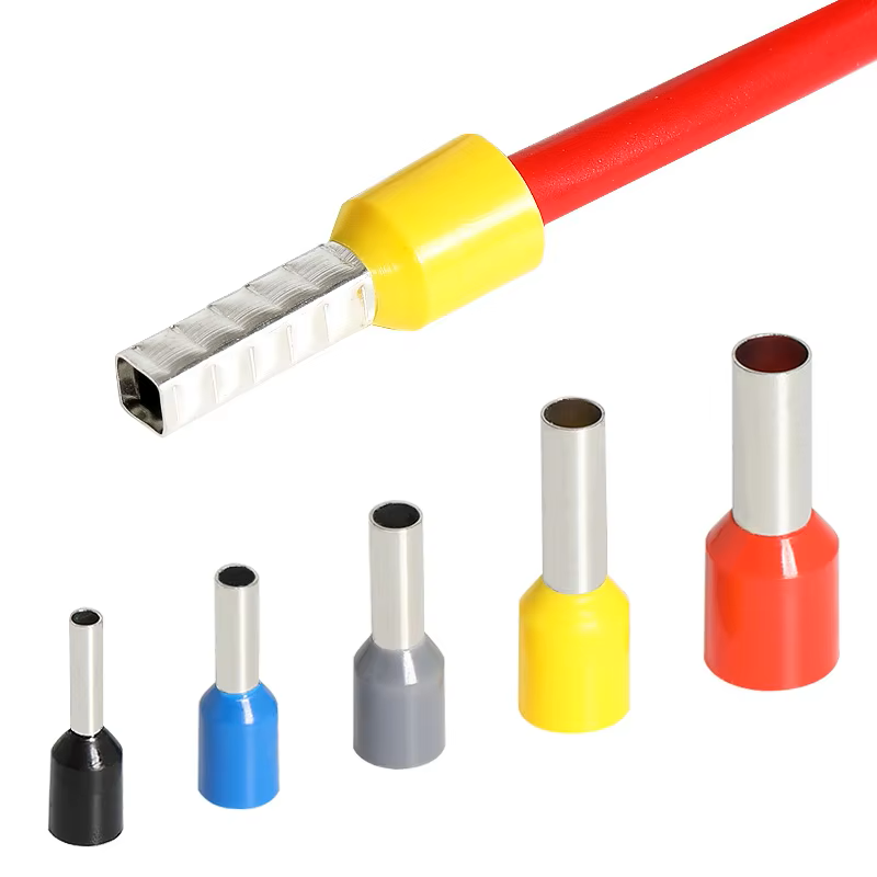
Square crimp ferrules are preferred
To ensure IP rating is retained, a sheathed cable with diameter suitable for use with the cable gland insert should be used. Three cable gland seals are supplied as specified in the table below. The gland with the single hole should be used when a single cable is required; the gland with two holes should be used where two cables are required etc. Cable seals are manufactured using NBR (Nitrile Butadiene Rubber) and are resistant to oils and biological oils, solvents and most industrial chemicals. Always check the suitability of the cable gland insert with all chemicals found in the operating environment.
Part No |
No. holes |
Hole diameter |
Cable |
|
A |
1 |
11mm |
6-11mm |
|
B |
2 |
5mm |
3-5mm |
|
C |
3 |
4mm |
2-4mm |
|


To assemble the gland, insert the gland insert into the gland claw, and tighten the compression nut to create a seal.
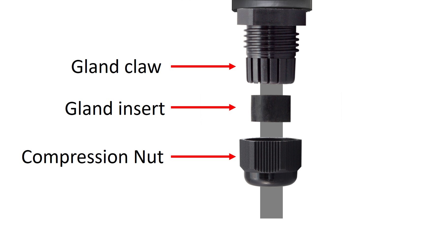
Gland assembly instruction
Initial Setup
Initial setup can be performed using the integrated web-server using any Wi-Fi enabled phone, tablet or computer or with the Senquip connect App with an Android or iOS device. Once the device is connected to a network, it is recommended that configuration be continued using the Senquip Portal.
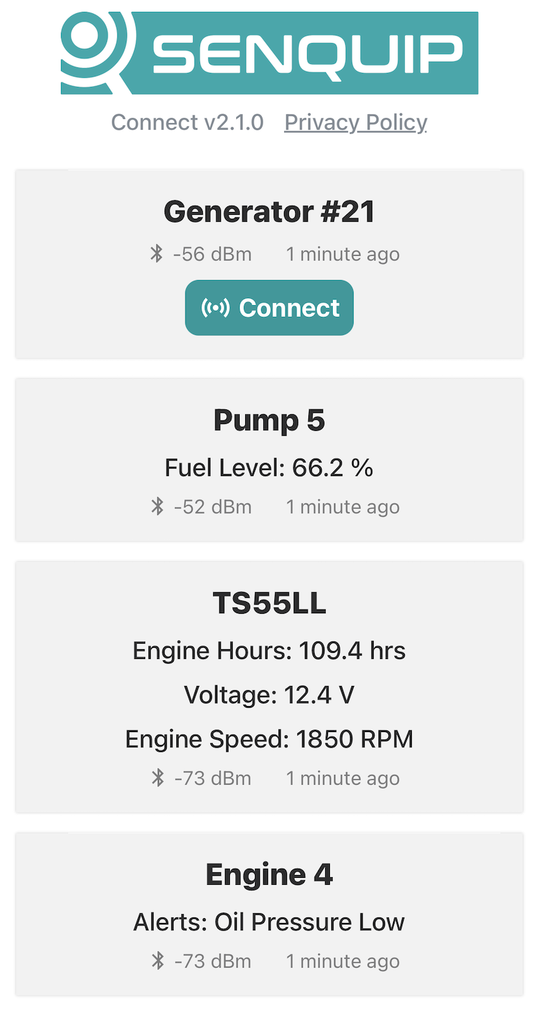
Senquip Connect App
Note
For volume opportunities, devices can be pre-configured to connect immediately to a network; please contact Senquip to discuss this option.
With the cover open, two push-button switches (setup and reset) and two LEDs (network and status) are available. The switches and LEDs are used to configure the device.
Buttons and LEDs for setup
LED Indicators
The GREEN status LED and ORANGE network LED indicate the current state of the ORB-C3. These LEDs are only active if the lid is open. When the lid is closed, the LEDs will remain off to conserve energy. A summary of LED function is given in the table below.
Note
During normal operation, the LEDs will be off when the device is sleeping or hibernating and will not turn on when the lid is opened until the next measurement interval.
Status LED |
Network LED |
Meaning |
|---|---|---|
(Green) |
(Orange) |
|
Off |
Off |
Device is sleeping or lid is closed |
Flash (1Hz) |
Off |
Setup Mode |
On |
Flash (1Hz) |
Searching for network |
On |
Pulse off (2 sec) |
Attached to network (Wi-Fi or LTE), but not connected to Senquip Portal |
On |
On |
Attached to network and connected to Senquip Portal |
Fast Flash |
Fast Flash |
Factory reset in progress |
Off |
Fast Flash |
Firmware update in progress |
Slow Flash |
Off |
Pre-charge mode |
Note
Opening the enclosure activates the internal tamper switch, causing the LEDs to illuminate. Alerts can be configured to report enclosure access.
Firmware Updates
The latest firmware version and a description of changes to firmware can be found in the Senquip Device Firmware Changelist.
Updating to the latest firmware can be performed from the Senquip Portal by selecting Settings and Update and then pressing the Update Firmware button. To update to a specific firmware version, enter the exact firmware number and press Update Firmware. During the firmware update, the orange network LED will flash fast. After a firmware update, the LEDs may freeze or remain off for a few minutes. This is normal behaviour and occurs shortly after firmware update when the ORB-C3 is encrypting the memory.
The firmware update can be seen in the command queue and has been received by the device when the status shows as success. Receipt of the firmware update by the device does not always mean that the update is correctly applied. To ensure that the update has occured, check the firmware number in the Device Info widget on the device Portal page. You may need to refresh the browser window.
Factory Reset
To perform a factory reset, press and hold the Setup button. While holding the Setup button, press and release the Reset button. The green status LED and orange network LED will begin to flash fast. Continue to hold the Setup button down for 10 seconds. After 10 seconds, the LEDs will stop flashing at which point the Setup button can be released. All settings will be changed back to the factory state and the device will restart. Any firmware updates made to the device will be preserved.
Warning
Returning the device to factory defaults will remove all network settings, rendering remote updates impossible.
Passwords
Each ORB-C3 is supplied with unique factory-generated credentials that protect access to the device and simplify commissioning.
The credentials are generated using a cryptographically secure random number generation process and are unique to each device.
The device is supplied with a credentials card located inside the enclosure containing:
Device ID
Setup Password (SETUP PASS)
Wi-Fi Access Point Password (WIFI PASS)
Quick Add QR code
Quick Start Guide QR code
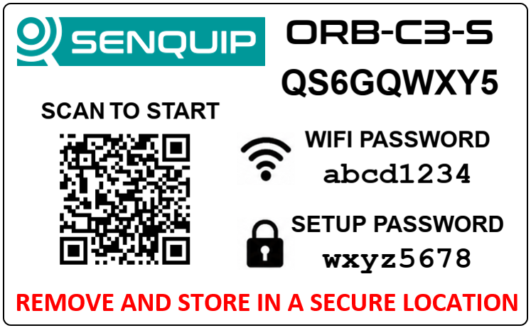
Device credentials card
The Device ID uniquely identifies the device within the Senquip Portal.
The Setup Password is used to access device settings through the Senquip Connect App or device webserver while the device is in setup mode. The Setup Password may also be used to establish administrative access to a device if no administrator has yet been assigned.
The Wi-Fi Password protects access to the device’s Wi-Fi Access Point when local wireless configuration is required.
The Quick Add QR code contains the Device ID and Setup Password, allowing an authenticated Senquip Portal user to add the device to their account with a single scan.
The Quick Start Guide QR code links to the latest installation and commissioning instructions for the device.
Warning
Store the credentials card in a secure location. Anyone with access to the Device ID and Setup Password may be able to establish administrative access to the device.
Password Management
Authorised administrators may change the Setup Password and Wi-Fi Password through the Senquip Portal.
If a password is forgotten, an administrator may retrieve the current password through the Senquip Portal following identity verification.
Factory Reset
A factory reset restores device settings to their factory defaults, including the factory default passwords.
A factory reset does not change device ownership, user permissions, or the device identity recorded by the Senquip Cloud.
Administrative Recovery
If all administrator accounts are inadvertently removed from a device, administrative access may be re-established using the Setup Password.
Where appropriate verification can be completed, Senquip may also assist in restoring the original administrator account associated with the device.
Setup Mode
Setup Mode enables local configuration of the ORB-C3 using either the Senquip Connect App via Bluetooth or the device’s embedded web server via Wi-Fi.
Entering Setup Mode
To enter Setup Mode, power the ORB-C3 and wait for the green Status LED to become solid. Press the Setup button. When the green Status LED starts flashing, the device is in Setup Mode.
If connected to external power, the ORB-C3 will remain in Setup Mode while the lid is open. If external power is not available, the ORB-C3 will enter sleep mode after 10 minutes of inactivity. To re-enter Setup Mode, press the Setup button again for 2 seconds.
Setup Mode is exited once the lid has been closed for more than 10 seconds.
Configuring the Device
Once the ORB-C3 is in Setup Mode, local configuration can be performed using either:
Senquip Connect App (recommended) - connects to the ORB-C3 via Bluetooth.
Embedded Web Server - connects to the ORB-C3 via its Wi-Fi access point using a web browser.
For detailed instructions on using either method, see First Connection.
Note
Once a network connection has been established, it is recommended that further device configuration be performed remotely using the Senquip Portal.