External Sensors
Inputs and Outputs
The UNI provides two configurable input/output (IO) channels that can be used for measuring voltages, counting pulses, measuring frequency and duty cycle, controlling external devices, and interfacing to 1-Wire sensors.
Pin |
Name |
Description |
|---|---|---|
4 |
IO1 |
Digital input, pulse input, 1-Wire, and output |
5 |
IO2 |
Voltage input, and output |
The available functions are summarised below.
Function |
IO1 |
IO2 |
|---|---|---|
Digital measurement |
X |
|
Voltage measurement |
X |
|
Pulse count |
X |
|
Frequency |
X |
|
Duty cycle |
X |
|
Wake on change |
X |
|
Switch to GND |
X |
X |
Pullup |
X |
|
1-Wire |
X |
General IO Settings
Each IO can be configured independently.
Measurement Interval
Measurements can be scheduled as a multiple of the base interval. The fastest possible measurement rate is achieved by setting the Interval to 1, in which case measurements will occur on every base interval. To reduce power consumption, the measurement rate can be reduced by increasing the Interval. To disable an IO, set the Interval to 0.
Default State
The default state determines the output state of an IO between measurement cycles.
Note
The state of an IO may deviate from the settings if being controlled by a script.
Measurement State
The measurement state determines the state of an IO during a measurement cycle.
Measurement Time
The measurement time determines how long the device hold the IO in the measurement state before taking a measurement. This allows attached sensors to boot, or for measurements to settle before being measured.
IO1
IO1 supports digital measurement, pulse counting, frequency measurement, duty cycle measurement, wake-on-change, 1-Wire communications, and output switching.
Digital inputs are measured using a threshold of approximately 2V. Voltages below the threshold are interpreted as OFF and voltages above the threshold are interpreted as ON.
Pulse counting can be used with flow meters, rain gauges, energy meters, run sensors, and other pulse-output devices. Frequency and duty cycle measurements use the same pulse measurement circuitry.
Many pulse-output sensors, including reed-switch flow meters and rain gauges, use open-collector outputs or voltage-free contacts that switch to ground. In these applications, the internal pullup resistor can be enabled to provide the required bias voltage for pulse detection.
For low-power applications, IO1 may be configured to wake the device when the input changes state.
IO2
IO2 supports voltage measurement, wake-on-change, and output switching.
Voltage measurements may be calibrated into end-use engineering units. For example, a 0-10V level transmitter representing a water level of 0-1m can be configured so that the measured value is reported directly in metres. This allows sensor outputs to be displayed and alarmed in meaningful application units rather than raw voltages.
For low-power applications, IO2 may be configured to wake the device when the input changes state.
Output Functions
The IO can also be used as outputs and can be switched to:
OFF - High impedance.
GND - Connects the IO to ground.
PULLUP - Enables an internal pullup resistor (IO1 only).
OFF disconnects all internal sources from the IO, leaving the pin in a high impedance state.
GND connects the IO to ground through a protected low-side switch and is typically used to activate relays, alarms, indicators, contactors, and other externally powered devices.
PULLUP enables an internal pullup resistor to 3.3V and is typically used with voltage-free contacts, reed switches, and open-collector outputs.
Output Characteristics
Each IO output can switch voltages up to 32V and sink currents up to 250mA.
The outputs are protected against overloads, short circuits, electrostatic discharge, inductive transients, and excessive temperature. If a fault condition occurs, the output automatically protects itself and will automatically resume operation when the fault is removed.
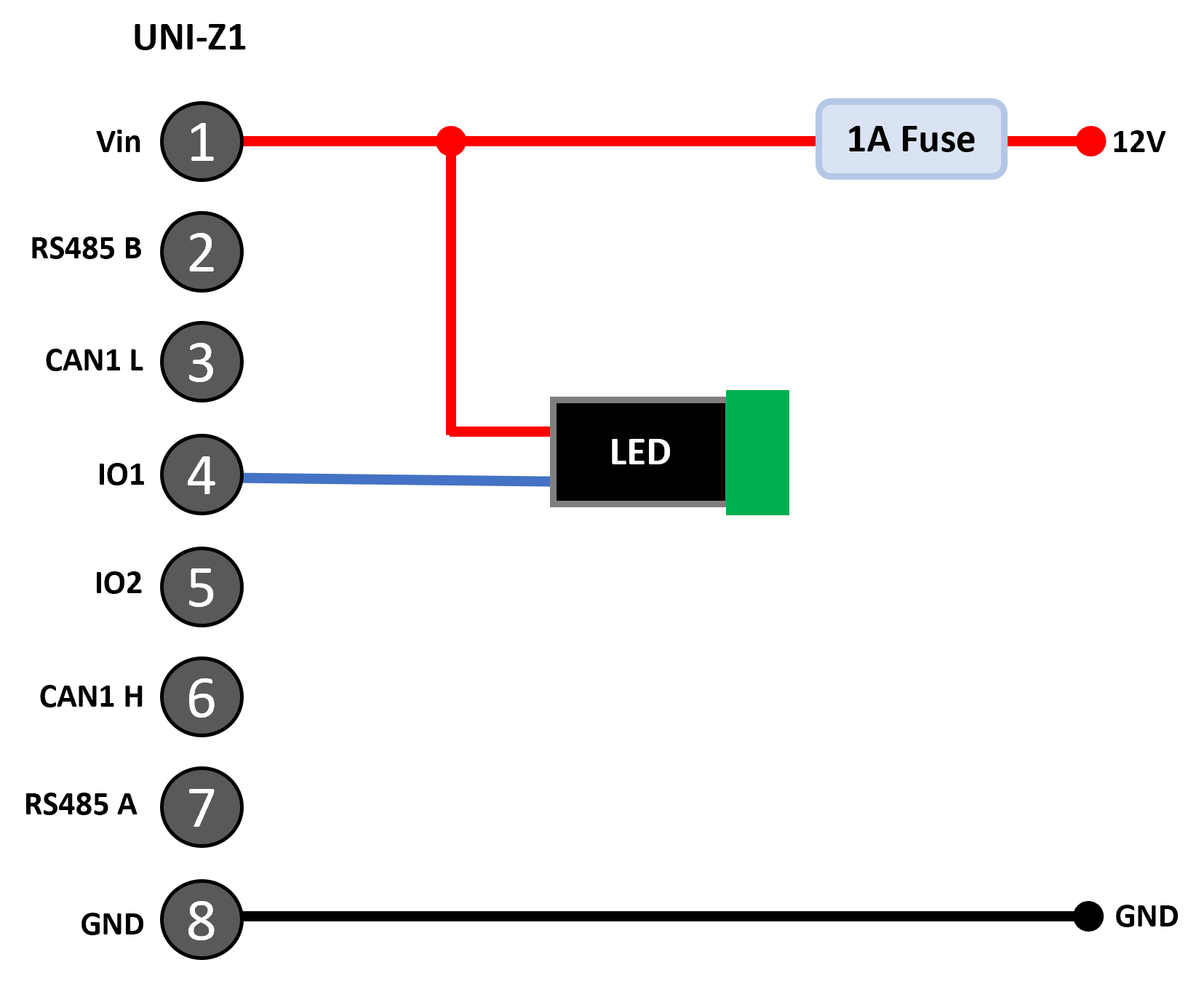
Switching a resistive load
The IO are capable of switching inductive loads such as relays and solenoids; however, flyback diodes should always be fitted to inductive loads to minimise electrical stress and improve system reliability.
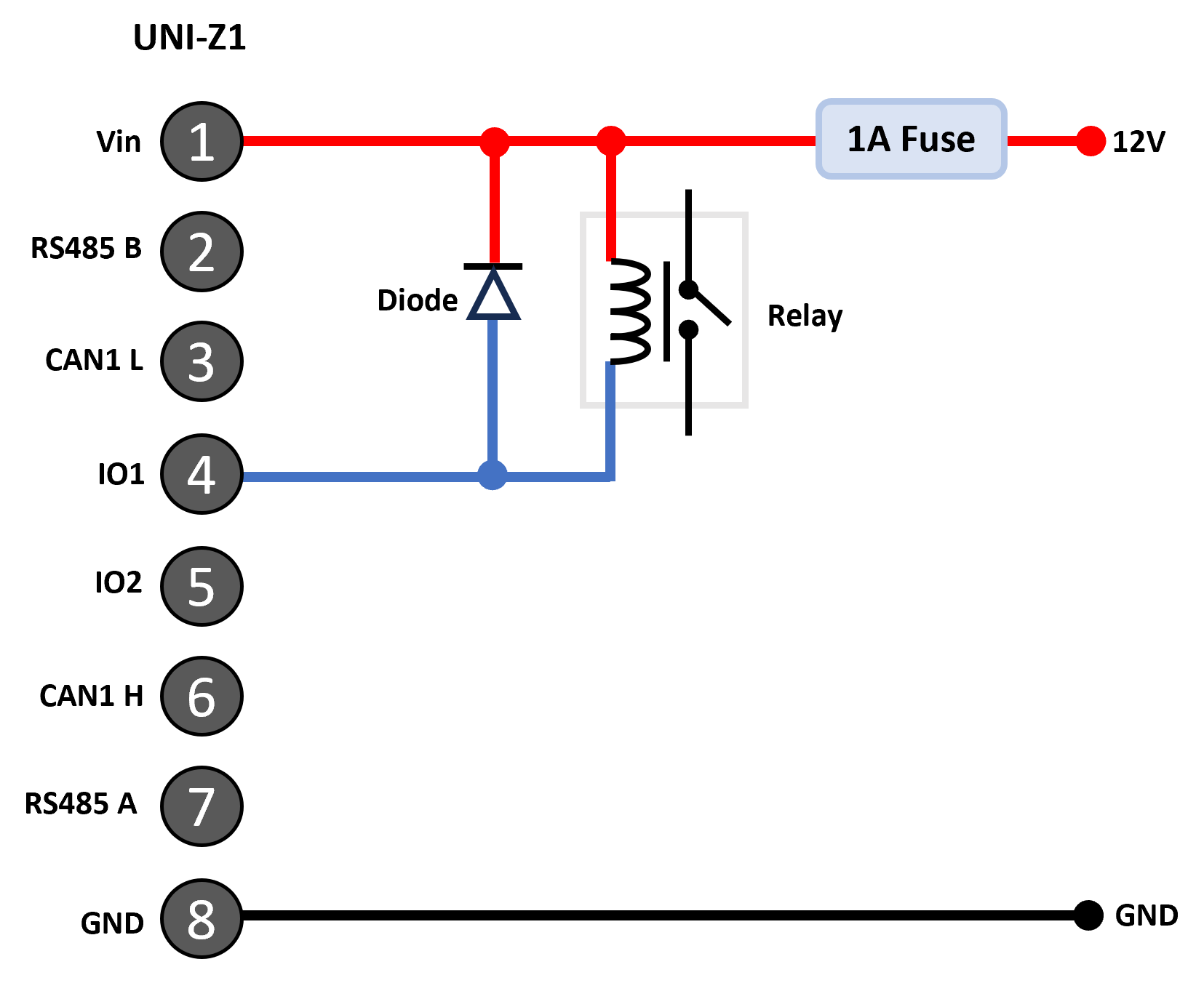
Switching a high inductance load
Pulse Counting
IO1 can be used to measure pulse count, frequency, and duty cycle.
Pulse counting records the number of input transitions occurring during the measurement period. Frequency measurement determines the pulse repetition rate, while duty cycle measurement determines the proportion of time the signal remains active.
Input transitions are detected when the signal crosses the digital input threshold of approximately 2V.
Note
Duty cycle is measured at the approximately 2V digital input threshold. For signals with significant rise and fall times, the measured duty cycle will depend on where the signal crosses this threshold.
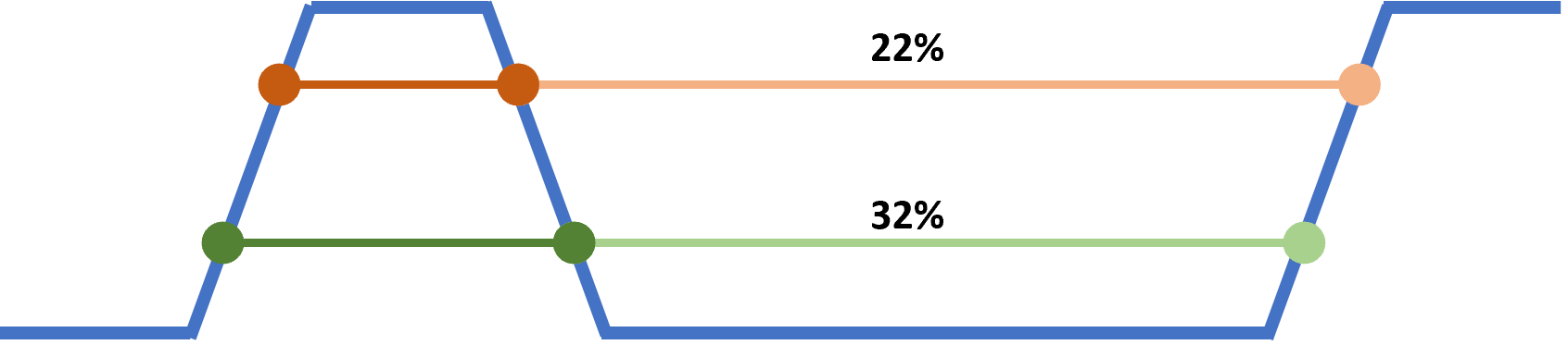
Effect of Rise and Fall Time on Duty Cycle Measurement
For reliable operation, input signals should transition cleanly through the threshold voltage and excessive noise around the threshold should be avoided.
The figure shows how to wire a flow meter with a reed-switch using the internal pullup on the UNI-Z1.
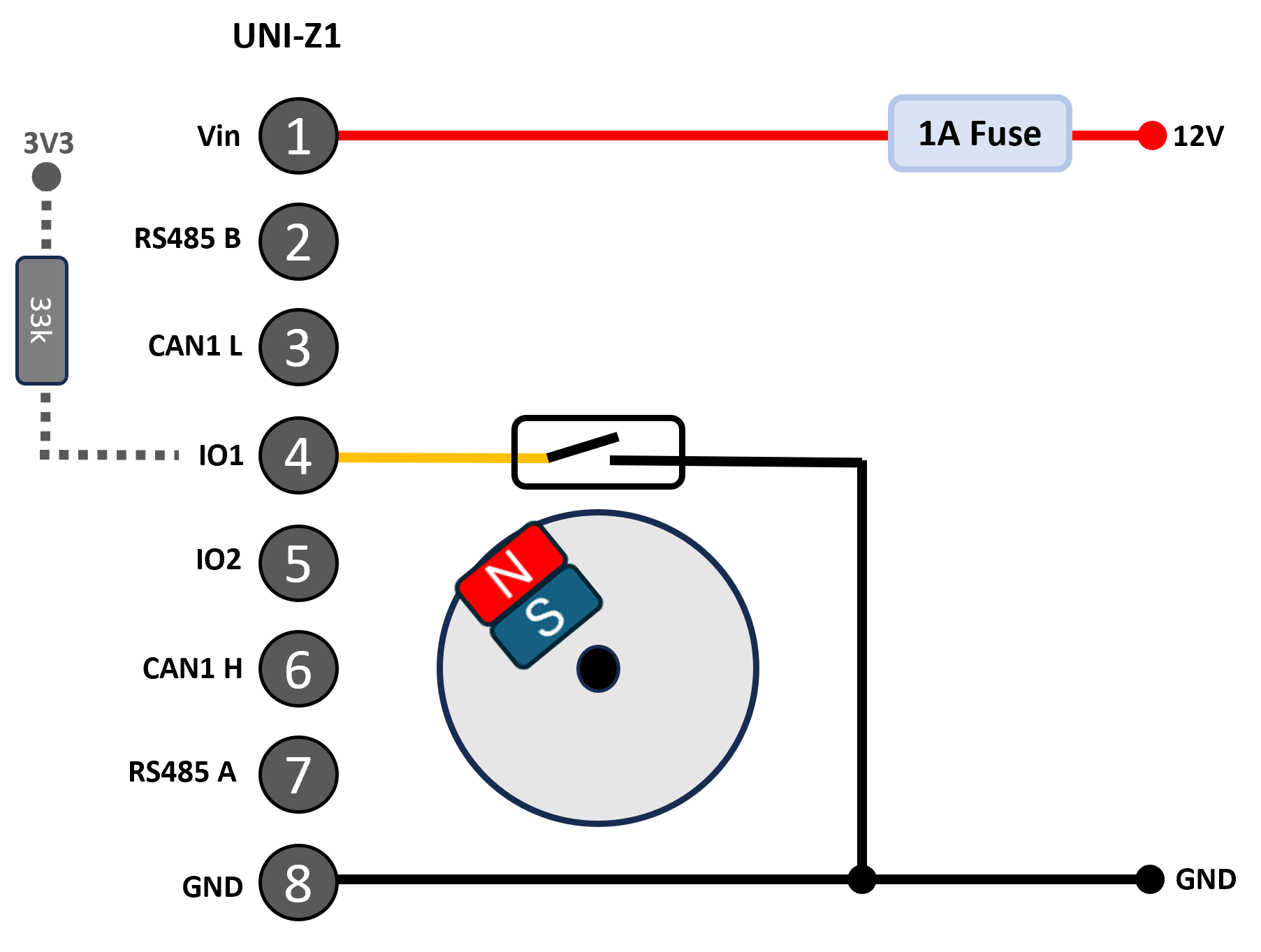
Pulse counting
Wake on Change
Wake-on-change allows the UNI to wake from low-power sleep modes when an input changes state.
This feature is particularly useful when monitoring alarm contacts, limit switches, float switches, reed switches, pulse-output sensors, and other event-driven inputs that require immediate response. In many of these applications, the internal pullup resistor on IO1 can be enabled, allowing the sensor to pull the input low when activated.
1-Wire
IO1 can be configured for 1-Wire communication by selecting 1WIRE as the IO1 Default State. When 1-Wire is enabled, IO1 is dedicated to 1-Wire operation and all other IO1 measurement and output functions are disabled.
1-Wire is commonly used by digital temperature sensors, identification devices, and other low-speed digital sensors.
The 1-Wire data line is connected to IO1. Multiple 1-Wire devices can share the same bus as each device contains a unique factory-programmed address.
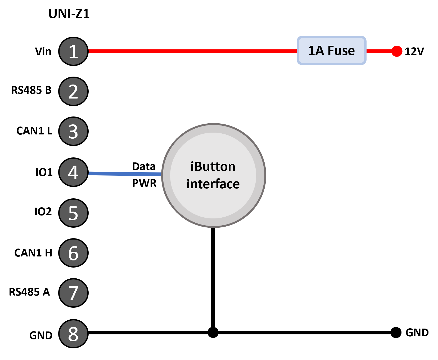
iButton reader connected to IO1
Communication with 1-Wire devices is performed entirely from script. The script is responsible for discovering devices, selecting addresses, issuing commands, reading responses, and dispatching measurements.
Note
Some 1-Wire devices support parasite power operation. Where reliable operation is important, powering sensors from an external supply is recommended.
Scripting
The IO can be controlled directly from scripts.
Scripts can read measurements and change output states.
Warning
If an IO is enabled in the settings and is also used in a script, the behaviour of that IO will be affected by both the settings and the script.
Note
In sleep and hibernate modes, the outputs default to OFF. If a pullup has been enabled, it will remain active during sleep and hibernate.
Specification
Parameter |
Specification |
|---|---|
IO1 Characteristics |
|
Open circuit voltage maximum |
32V |
Pullup resistor (always on) |
2.7k ohm to 3.3V |
IO voltage guaranteed to be detected as low |
< 0.5V |
IO voltage guaranteed to be detected as high |
>2.5V |
IO2 Characteristics |
|
Open circuit voltage maximum |
32V |
Resistance to ground |
110k ohm |
Output (IO1 and IO2) |
|
GND sink current maximum |
250mA per pin |
Voltage Measurement (IO2) |
|
Voltage ADC Type |
12 bit SAR |
Voltage range |
0-32VDC |
Voltage measurement resolution |
10mV |
Voltage measurement accuracy |
TBD |
Threshold for IO to wake from hibernate |
2.0V +/-0.5V |
Frequency and Pulse (IO1) |
|
Frequency measurement range |
1Hz to 10kHz |
Frequency measurement accuracy |
1Hz |
Pulse counting minimum frequency |
0Hz |
Pulse counting maximum frequency - always on |
10kHz |
Pulse counting maximum frequency - sleep |
100Hz * |
Pulse counting pulse width minimum - always on |
300usec |
Pulse counting pulse width minimum - sleep |
5msec |
Duty cycle measurement range |
2% to 98% (tested at 100Hz) |
Duty cycle accuracy |
+-1% (tested at 100Hz) |
Note
The maximum pulse counting frequency in sleep assumes a 50% duty-cycle square wave. Higher pulse counting frequencies may be supported at the expense of increased power consumption. Contact support@senquip.com if higher pulse counting frequencies are required during sleep.
Serial interface
The serial port can be used to capture data that is sent from an external system or to interface to a MODBUS sensor.
The UNI-Z1 provides an RS485 interface on pins 2 and 7 of the header. The pin functions are shown in the table below. When required, an optional 120Ω termination resistor can be enabled in the settings.
Pin |
Function |
|---|---|
2 |
RS485-B |
7 |
RS485-A |
Note
RS485-B is sometimes referred to as D+ or TX+/RX+ and RS485-A as D- or TX-/RX-.
The serial interface supports RS485 operation.
The interface incorporates protection features to improve robustness and reliability in industrial environment with the RS485 receiver offering full failsafe operation for floating, shorted, or terminated inputs.
Specification
Parameter |
Specification |
|---|---|
RS485 differential output voltage (minimum with load resistance 120Ω) |
+2V |
RS485 differential input threshold (typical) |
+/-200mV |
Maximum nodes in RS485 mode |
256 |
RS485 termination resistor |
120Ω |
ESD protection |
+/-16kV |
Settings
Measurements can be scheduled as a multiple of the base-interval. The fastest possible measurement rate is achieved by setting the interval to 1 in which case measurements will occur on every base interval. To reduce power consumption, the measurement rate can be turned down by increasing the interval.
In serial capture mode the measurement interval can be used to reduce the number of readings being provided by a connected sensor or system that may be permanently powered. If for instance, a connected system is sending a message every second but it is only required to be read and transmitted every minute, the measurement interval can be set to 1 minute in which case the device will wake on the minute interval, receive a message and return to sleep thereby missing the other 59 messages sent by the attached system. Since serial packets cannot be interrogated by the UNI-Z1 without a customised script, it makes sense to set the measurement interval to the same as the transmit interval in most cases.
An optional 120Ω RS485 termination resistor can be selected by selecting the Termination resistor option. The purpose of the termination resistor is to match the impedance of a transmission line to the hardware impedance of the interface to which it is connected. Termination is generally not required in lower speed networks (9600 baud or less) and networks shorter than 500m in length. No more than 2 termination resistors should be used, one at each end of the RS485 transmission line.
A baud rate of 4800, 9600, 19200, 38400, 56800 or 115200 needs to be selected using the baud rate option. Other settings, including the number of bits, odd or even parity and 1 or 2 stop bits are added in the settings field. The most common setup is 8 bits, no parity and 1 stop bit or “8N1”.
The serial interface can be configured in serial capture mode or MODBUS mode using the mode option. Capture mode is typically used where an external sensor sends serial data and a portion of that serial data is to be captured. MODBUS mode is used to connect to external sensors that are compatible with the MODBUS standard.
In serial capture mode The device listens for periodic data and when received, transmits this data at the next send interval. The maximum length of a message that can be captured is 512 characters. Once 512 characters have been received, the UNI-Z1 will terminate the capture and will transmit it on the next transmit interval.
In capture mode, the max-time setting can be used to set a timeout after which the serial port will return to sleep. Max-time can be used as a way to end serial measurement in the event that no serial data is received, or as a mechanism to allow the device to sample the serial port for a defined time-period.
Note
If the serial port needs to be kept on all the time, set the max-time to longer than the measurement interval. The contents of the serial buffer is retained as long as the device does not return to sleep.
The operation of the max chars option is similar to the max time setting except that the serial port stops sampling after a certain number of characters has been received. In most cases where the max-chars setting is used to terminate serial capture, the max-time setting is also used to end the serial measurement in the event that data does not arrive.
In Serial capture mode, in systems where many messages are sent and only a few are of interest, a start string of up to 10 characters can be enabled. For instance, in a typical GPS serial NMEA feed, the following are a subset of available messages:
DTM - Datum being used.
GGA - Fix information
GLL - Lat/Lon data
GSA - Overall Satellite data
GSV - Detailed Satellite data
RMC - Recommended minimum data for GPS
RTE - Route message
VTG - Vector track an Speed over the Ground
If in the application, the user is only interested in receiving the GGA message, then a start string can be set to GGA. In that way, any messages starting with DTM, GLL, GSA or other unwanted messages will be discarded.
Note
If a start string is enabled, the device will stay awake until the string is received or until the max-time is reached.
In firmware revisions less than 2, serial start strings are specified as text, with special characters such as carriage return and line feed being specified by their respective escape sequences. A list of allowable escape sequences is given below:
\f Form-feed
\n Newline (Line Feed)
\r Carriage Return
\t Horizontal Tab
\v Vertical Tab
\\ Backslash
Note
Because escape sequences start with a backslash (\), if a capture string contains a backslash, it needs to be escaped and so is represented as a double backslash (\\).
In firmware release 2 and above, serial start strings are specified as text, with special characters such as carriage return and line feed being specified by their respective ASCII codes in hexadecimal. A list of example hexadecimal sequences is given below:
\x0C Form-feed
\x0A Newline (Line Feed)
\x0D Carriage Return
\x09 Horizontal Tab
\x0B Vertical Tab
\x08 Backslash
The change to the method used to represent special characters has been made to allow for all ASCII characters to be used, and to allow for hexadecimal data to be captured.
Note
In firmware revisions 2 and lower, special characters are specified as escape characters. In revisions 2 and above, special characters are represented by their ASCII representations in hexadecimal.
In some serial protocols, the start of a packet is specified by a preceding period of inactivity on the serial bus. The Idle Time Before Start parameter can be used to specify an idle time, which is exceeded will trigger the serial port to start capturing serial data.
Note
If the serial port is capturing data and a subsequent idle time occurs, the capture process will restart and captured data will be discarded.
A serial capture stop string of up to 10 characters can also be provided. Again using the NMEA example, all NMEA messages end with a carriage return and line feed and so the serial capture stop strings in each case will be the same and will be “\r\n” or \x0D\x0A in revision 2 and above firmware. In most instances, the serial stop strings will be the same for all messages.
Note
If a start string is specified without a stop string, or the stop string is never encountered, the serial port will capture characters until the max-time or max-chars is reached, the next measurement interval occurs or 256 characters are received.
An optional serial request string can be sent, on each measurement interval, to an external device. The purpose of the request sting is to request data from an external sensor or system. The request string can be a maximum of 10 characters and can be entered as text. Special characters like carriage return and line feed can be inserted using escape sequences or their ASCII representations as described earlier in the chapter.
The UNI-Z1 implements the MODBUS communications protocol standard as a master, which enables communication with many slave devices connected to the network. The UNI-Z1 can be configured to periodically request specific data from slave MODBUS devices on the network and transmit that data at specified intervals.
Up to fifty MODBUS data requests can be configured; these data requests can either be from individual slave devices or multiple requests from the same device. For each of the fifty data reads, the slave address, function and register address need to be specified. The slave address will be specified by the manufacturer of the device that is attached to the UNI-Z1; in some cases, slave devices allow their addresses to be configured. The function specifies the type of data to be read from the slave device. The UNI-Z1 supports the following types of data reads:
Disabled - the particular MODBUS channel is not used
Read Coil - a 1 bit data value
Read Discrete - a 1 bit data value
Read Holding - a single 16 bit holding register
Read Input - a 16 bit input register
Read Holding (32 bits, Little Endian register order) - a 32 bit holding register
Read Holding (32 bits, Big Endian register order) - a 32 bit holding register
Read Input (32 bits, Little Endian register order) - a 32 bit input register
Read Input (32 bits, Little Endian register order) - a 32 bit input register
Endianness is the order or sequence of bytes of digital data in computer storage and will be specified by the sensor that is being connected to the UNI-Z1.
A single MODBUS device may have multiple data values that can be read. The register address specifies which data the slave device needs to deliver.
In MODBUS mode, calibration can be applied so that the registers read by the UNI-Z1 can be scaled to be in the units of what is being measured. For instance, a register that returns 0 to 255 may represent 0% humidity to 100% humidity. The UNI-Z1 can be calibrated to take a number and to convert it to humidity in % and return that as the measured value.
In any system, the sensor and possibly the measured value will be subject to errors that may accumulate to reduce accuracy. In a system that uses the UNI-Z1 to measure fluid volume in a 100 litre tank using a MODBUS sensor, the sensor may have offset errors such that with zero liquid in the tank, the UNI-Z1 is showing a small volume. The UNI-Z1 and sensor may also not be perfectly linear in that they may not measure 1 litre in exactly the same way when the tank is empty versus when it is full. The tank itself may also not be perfectly manufactured and may, for instance have walls that are not perfectly straight. All of these errors could add together such that the final system is less accurate than expected. To achieve a more accurate system, a calibration can be performed. In this example, the tank could be calibrated by adding a small amount of liquid, say 10 litres (low Y) and noting the value reported by the UNI-Z1 (low X). Now fill the tank by adding another 99 litres (high y) and note the value being reported by the UNI-Z1 (high X). By filling the high and low X and Y values into the calibration constants associated with analog mode, offset and non-linearity errors can be eradicated, resulting in a much more accurate system.
In MODBUS mode, warning and alarm thresholds for can be set for each MODBUS channel. Once enabled, each time a measurement is completed, the returned value will be compared with minimum and maximum warning and alarm thresholds. If a warning or alarm level is breached, a message will immediately be transmitted. As long as the warning or alarm condition persists, messages will be transmitted at the exception-interval rather than the transmit-interval.
Note
If calibration has been applied, then the warning and enable thresholds are in the calibrated units.
A full list of serial interface settings is given in the table at the end of the chapter.
CAN Bus interface
The Senquip UNI-Z1 is equipped with CAN bus that can be used to read data from all kinds of vehicles and sensors. Many sensors, controllers, and electronic devices can be connected to a single CAN network.
In many cases, the protocol that is being used on the CAN bus is known, and so large volumes of understandable data can be extracted from all kinds of vehicles. Common CAN protocols include:
J1939, the dominating CAN-based protocol for trucks and busses.
ISO 11783, a J1939 flavor for agricultural tractors.
ISO 11992, an interface between trucks and trailers.
NMEA 2000, a protocol based on J1939 for marine use.
CANopen, provides a standard for industrial machinery commonly used in industrial automation.
The CAN interface on the UNI-Z1 supports Classical CAN. Pins 3 and 6 provide the CAN interface, with pin 6 being CAN High (dominant high) and pin 3 being CAN Low (dominant low).
Pin |
Function |
|---|---|
3 |
CAN1 L |
6 |
CAN1 H |
In CAN networks, 120Ω termination resistors are installed at each end of the network. In most installations, the required termination will already be present and the internal termination resistor should remain disabled. If the UNI-Z1 is located at the end of a CAN network and termination is required, the internal termination resistor can be enabled in the CAN settings. No external termination resistor is required.
Warning
In CAN bus systems, the ground supplied to the Senquip UNI-Z1 must be the same ground as used by the CAN network. High differential voltages between the CAN lines and ground can damage the CAN interface.
Specification
Parameter |
Specification |
|---|---|
CAN physical layer |
High-speed CAN (ISO 11898-2 compatible) |
Supported protocols |
Classical CAN 2.0A and 2.0B |
Maximum bit rate |
1Mbit/s |
Receiver common mode range |
+/-30V |
Bus fault protection on CAN High and CAN Low |
+/-58V |
ESD protection, CAN bus pins, contact discharge |
+/-8kV |
ESD protection, CAN bus pins, air discharge |
+/-15kV |
Optional termination resistor |
120Ω |
Settings
Measurements can be scheduled as a multiple of the base-interval. The fastest possible measurement rate is achieved by setting the interval to 1 in which case the CAN network will be sampled on every base interval. To reduce power consumption, the measurement rate can be turned down by increasing the interval.
The CAN bus peripheral on Senquip devices supports can bit rates of 125kbit/s, 250kbit/s, 500kbit/s and 1Mbit/s as specified in the Nominal Baud Rate field.
Configurable internal 120Ω termination resistors can be enabled.
To ensure minimum intrusion on CAN systems, the CAN peripheral can be set to listen only. In this mode the Senquip device will only receive messages that are acknowledged on the bus by a listening node. Where required, the Senquip device can be made to acknowledge messages by selecting the TX Enable option.
The Capture Time setting can be used to set a timeout after which the CAN bus peripheral will stop listening, allowing the Senquip device to transmit received messages and return to sleep. capture-time can also be used as a mechanism to allow the CAN peripheral to sample the CAN bus for a defined time-period.
A full list of CAN bus settings is given in the table at the end of this chapter.
CAN Filters
Most automotive CAN networks transmit hundreds of different messages, each with a unique identifier. The Senquip device allows you to filter and capture only the messages you need using the ID Capture List.
Basic Usage
Enter the CAN IDs you want to capture in hexadecimal, separated by commas. For example:
18FF20F2,18FF36F0,18FF1BF2
During each measurement interval, the device listens for the listed messages until either all are received or the Capture Time expires.
Capturing Multiple Messages
To capture multiple messages with the same ID, use * followed by the number of each message requied:
18FF20F2*4,18FF1BF2*10
This captures:
4 messages with ID
18FF20F210 messages with ID
18FF1BF2
To capture all messages of a certain ID received during the interval, use * without a number:
18FF1F12*
Wildcards and Advanced Filters
??can replace the Priority or Source Address in a J1939 ID.For example:
??FECA??
This matches any J1939 message with a PGN of
FECA, regardless of Priority or Source Address.#can be placed at the end of the list to match one of any other message not already listed:18FE1451*4,18FE1256*2,#
This captures:
4 messages with ID
18FE14512 messages with ID
18FE12561 of every other unique ID not already matched
Special Cases
Leave the list
blankto capture one of every message that arrives.Use a single
*to capture all messages, in the order they arrive.Warning
Capturing all messages may overwhelm the device in high-traffic CAN systems. The number of messages that can be captured in a measurement cycle is internally limited to 128.
Sending CAN Messages
CAN messages can be sent to connected device from within a script. The messages can be sent once, or can be set to repeat at a given time interval. If the device enters sleep or hibernate, repeating messages will be stopped. If the Senquip device is reset, the sending of repeating CAN messages is unaffected. The messages will continue to be sent until a change is applied. For example, if new script is loaded, forcing a reset, the CAN messages will continue to be sent until the new script applies a change. In the case of a malfunction that lasts for more than 30 second, repeating CAN messages will be stopped.
Note
To send CAN messages, the TX Enable option must be selected.
Calibration
Calibration can be applied to each measurement so that the value returned by the Senquip UNI-Z1 is in units that are meaningful in the end application. For instance, a fuel level sensor that outputs a voltage between 0 and 5V may represent a level between 0 and 100 litres of diesel. The voltage measurement can be calibrated to convert from Volts to the more meaningful unit of litres.
In any system, the measurement instrument (the Senquip UNI-Z1), the sensor and possibly the measured value will be subject to errors that may accumulate to reduce accuracy. In a system that measures fluid volume in a 100 litre tank using a 4-20mA sensor, offset errors may result in a non-zero or negative reading when the tank is empty. Sensor gain may also not be perfectly linear and so a 1 litre change may be measured differently when the tank is empty versus when it is full. The sensor may report in inches of liquid height where a more meaningful unit may be litres. To achieve an accurate and meaningful measurement, a calibration can be performed.
In this example, the tank could be calibrated by adding a small amount of liquid, say 10 litres at which point the current measured may be 4.1mA. Now add more liquid to take the level to say 80l. The sensor now reads 16.2mA. The calibration would then be filled into the IO setting as shown below:
Low In |
4.1 |
This is the value in mA measured by the Senquip UNI-Z1 |
Low Out |
10 |
This is the actual value that we would like to report |
High In |
16.2 |
This is the value in mA measured by the Senquip UNI-Z1 |
High Out |
80 |
This is the actual value that we would like to report |
Unit |
l |
The unit to be reported is litres |
Unit Names and Symbols
The calibration Unit field supports plain text together with a number of commonly used engineering symbols. This allows measurements to be displayed using familiar units such as °C, m³, Ω, µS/cm and N·m.
The following characters are supported:
Letters: a-z, A-Z
Numbers: 0-9
Symbols: /, Ω, ·, µ, Δ, ±, ×, :, °, ², ³, ., %, _, -
Examples:
Unit |
Description |
|---|---|
V |
Volts |
A |
Amps |
°C |
Degrees Celsius |
°F |
Degrees Fahrenheit |
Ω |
Ohms |
kΩ |
Kilohms |
m³ |
Cubic metres |
m² |
Square metres |
µS/cm |
Microsiemens per centimetre |
N·m |
Newton metres |
kg/m³ |
Density |
%RH |
Relative humidity |
L/min |
Litres per minute |
When entering units on Windows, some special characters can be entered using their ALT codes on the numeric keypad.
Character |
Windows ALT Code |
|---|---|
° |
|
² |
|
³ |
|
µ |
|
± |
|
× |
|
The remaining symbols can be copied directly from this guide or inserted using the Windows Character Map (charmap.exe) or the Windows Emoji & Symbols panel(Win + .).
Character |
Description |
|---|---|
Ω |
Ohm |
Δ |
Uppercase Delta |
· |
Middle dot |
Warnings and Alarms
For each measurement type, high and low warning and alarm levels can be set. Once enabled, each time a measurement is completed, the returned value will be compared with low and high warning and alarm thresholds. If a warning or alarm level is breached, a message will immediately be transmitted. As long as the warning or alarm condition persists, messages will be transmitted at the exception-interval rather than the transmit-interval.
Note
If calibration has been applied, then the warning and alarm thresholds should be set in the calibrated units.
To set a high level warning or alarm level only, set the low level to a value that is impossible to achieve. For instance to set a high only warning at 50V, set the low warning to -1V which is an unachievable value.
Hysteresis
Hysteresis prevents repeated alarms when a measured value fluctuates near a threshold. The hysteresis value is applied on both sides of the configured threshold. For an upper alarm, the value must reach upper threshold + hysteresis to enter the alarm state, then fall to upper threshold - hysteresis to clear it. For a lower alarm, the value must fall to lower threshold - hysteresis to enter the alarm state, then rise to lower threshold + hysteresis to clear it. Between the two switching points, the alarm retains its current state. Hysteresis uses the measurement configured units.
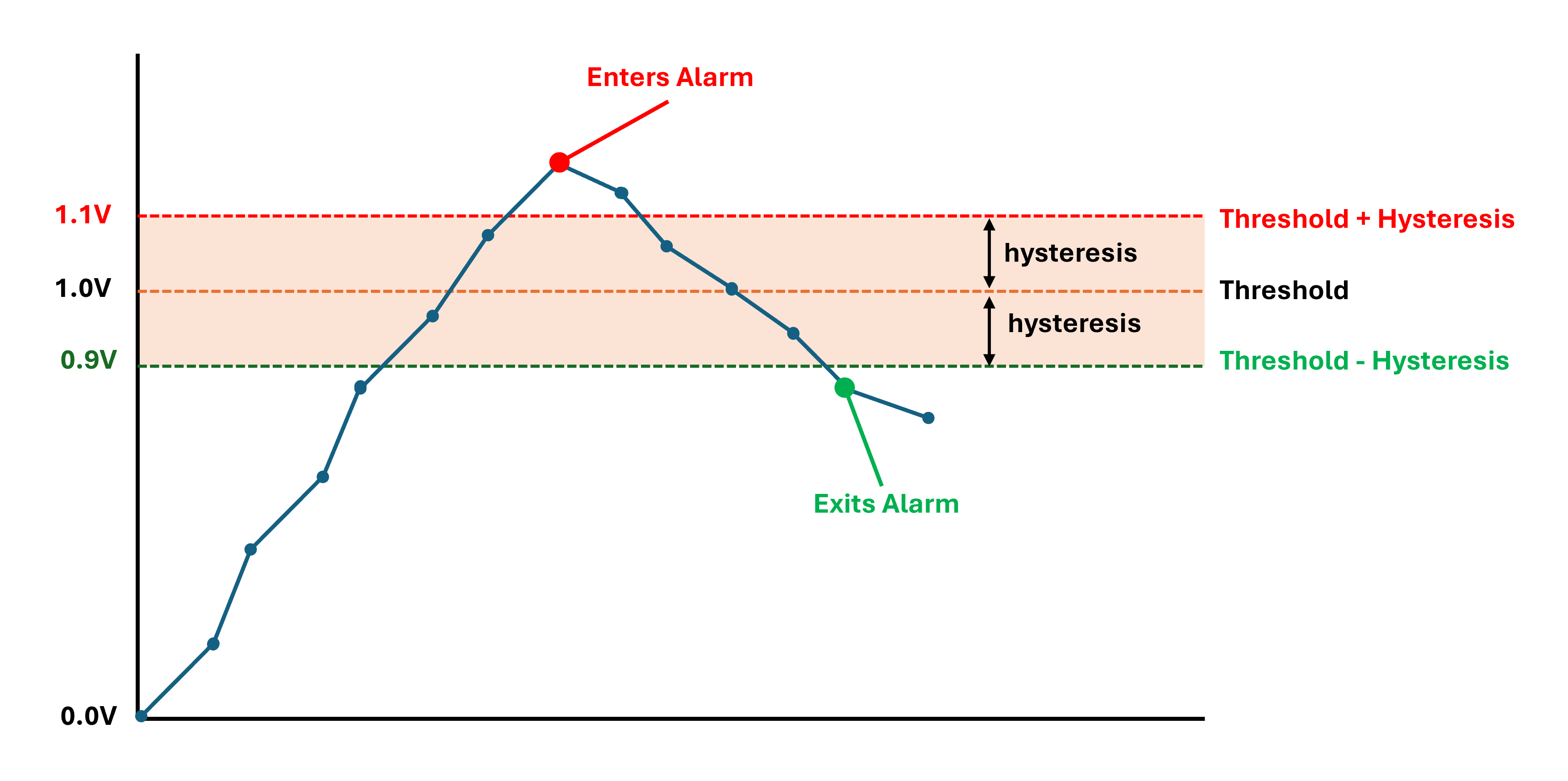
Upper alarm with a 1.0 V threshold and 0.1 V hysteresis. The alarm starts when the measured value reaches 1.1 V and clears when it falls to 0.9 V. Between those values, the alarm retains its current state.
External Sensor Settings
A full list of settings for external sensors is given in the table below.
Name |
Item |
Function |
Range |
Unit |
Internal Reference |
|---|---|---|---|---|---|
Input 1 |
|||||
Name |
text |
A name for the input that is meaningful to the user. |
25 chars |
input1.name |
|
Interval |
integer |
The number of base intervals after which the input is sampled. A value of 1 means that the input is collected every base interval. Set to 0 to disable. |
0 to 10000 |
input1.interval |
|
Mode |
preset |
Specifies the function of the IN1 terminal. The calibration, warnings and alarms are applied to this mode. |
input1.mode |
||
Digital 1 |
|||||
Digital Threshold |
decimal |
A threshold against which the input is compared to determine if the input state is ON or OFF. |
0 to 30 |
Volts |
input1.digital.threshold |
Digital Hysteresis |
decimal |
Once the input is in a certain state, hysteresis is the amount by which the input has to change before moving to the other state. |
0 to 20 |
Volts |
input1.digital.hysteresis |
Count Hours |
boolean |
Counts the number of hours the digtial input is ON (above threshold). |
input1.digital.count_hours |
||
Digital Change Alert |
boolean |
Sets whether a change in digital state generates an alert. |
input1.digital.alert.enable |
||
Analog 1 Calibration |
text |
Calibration parameters for Analog 1. Refer to user guide. |
30 chars |
input1.cal |
|
Unit |
text |
The unit of measure associated with the calibration. Examples: Litres/min, RPM, Volts |
input1.unit |
||
Warning |
text |
Warning thresholds. Refer to user guide. |
input1.warning |
||
Alarm |
text |
Alarm thresholds. Refer to user guide. |
input1.alarm |
||
Alarm/Warning Hysteresis |
decimal |
Once the input is in a certain state, hysteresis is the amount by which the input has to change before moving to the other state. |
input1.hysteresis |
||
Pulse Input |
|||||
Pulse Counting |
boolean |
Enables counting of pulses in addition to frequency measurement. |
input1.pulse.enable |
||
Reset Value |
integer |
The value at which the number of pulses counted on the input is reset to zero. |
1 to 2000000000 |
Counts |
input1.pulse.reset_value |
Pulse Scaling |
decimal |
Multiplier to convert the pulse count to a useful unit. |
input1.pulse.scaling |
||
Pulse Unit |
text |
The unit of measure associated with the scaled pulse count. Eg: Litres |
input1.pulse.unit |
||
Pulse Warning |
text |
Warning thresholds. Refer to user guide. |
input1.pulse.warning |
||
Pulse Alarm |
text |
Alarm thresholds. Refer to user guide. |
input1.pulse.alarm |
||
Input 2 |
|||||
Name |
text |
A name for the input that is meaningful to the user. |
25 chars |
input2.name |
|
Interval |
integer |
The number of base intervals after which the input is sampled. A value of 1 means that the input is collected every base interval. Set to 0 to disable. |
0 to 10000 |
input2.interval |
|
Mode |
preset |
Specifies the function of the IN2 terminal. The calibration, warnings and alarms are applied to this mode. |
input2.mode |
||
Digital 2 |
|||||
Digital Threshold |
decimal |
A threshold against which the input is compared to determine if the input state is ON or OFF. |
0 to 30 |
Volts |
input2.digital.threshold |
Digital Hysteresis |
decimal |
Once the input is in a certain state, hysteresis is the amount by which the input has to change before moving to the other state. |
0 to 20 |
Volts |
input2.digital.hysteresis |
Count Hours |
boolean |
Counts the number of hours the digtial input is ON (above threshold). |
input2.digital.count_hours |
||
Digital Change Alert |
boolean |
Sets whether a change in digital state generates an alert. |
input2.digital.alert.enable |
||
Analog 2 Calibration |
text |
Calibration parameters for Analog 2. Refer to user guide. |
30 chars |
input2.cal |
|
Unit |
text |
The unit of measure associated with the calibration. Examples: Litres/min, RPM, Volts |
input2.unit |
||
Warning |
text |
Warning thresholds. Refer to user guide. |
input2.warning |
||
Alarm |
text |
Alarm thresholds. Refer to user guide. |
input2.alarm |
||
Alarm/Warning Hysteresis |
decimal |
Once the input is in a certain state, hysteresis is the amount by which the input has to change before moving to the other state. |
input2.hysteresis |
||
Output 1 |
|||||
Name |
text |
A name for the input that is meaningful to the user. |
25 chars |
output1.name |
|
Interval |
integer |
Does not affect output mode. The number of base intervals at which the input is sampled. Set to 0 to disable. Set to 1 for every base interval. |
0 to 10000 |
output1.interval |
|
Mode |
preset |
Specifies the function of the OUT1 terminal. |
output1.mode |
||
Warnings |
boolean |
Determines if the output is turned on when a warning is active. |
output1.warnings |
||
Alarms |
boolean |
Determines if the output is turned on when an alarm is active. |
output1.alarms |
||
Alerts |
boolean |
Determines if the output is turned on when an alert is active. |
output1.alerts |
||
Hold Time |
integer |
Sets the time in seconds for which the output is held on after it is triggered. If set to zero, the output remains on while any exceptions are active. |
Seconds |
output1.hold_time |
|
Digital Change Alert |
boolean |
If enabled, a change in digital state will generate an alert. |
output1.digital.alert.enable |
||
Analog 3 Calibration |
text |
Calibration parameters for Analog 3. Refer to user guide. |
30 chars |
output1.cal |
|
Unit |
text |
The unit of measure associated with the calibration. Examples: Litres/min, RPM, Volts |
output1.unit |
||
Warning |
text |
Warning thresholds. Refer to user guide. |
output1.warning |
||
Alarm |
text |
Alarm thresholds. Refer to user guide. |
output1.alarm |
||
Alarm/Warning Hysteresis |
decimal |
Once the input is in a certain state, hysteresis is the amount by which the input has to change before moving to the other state. |
output1.hysteresis |
||
Thermocouple 1 |
|||||
Name |
text |
A name for the input that is meaningful to the user. |
25 chars |
tc1.name |
|
Interval |
integer |
The number of base intervals after which the thermocouple is measured and events are checked. A value of 1 means that the input is collected every base interval. Set to 0 to disable. |
0 to 10000 |
tc1.interval |
|
Hysteresis |
decimal |
The amount by which the measured value has to drop below the threshold to re-enable the event. |
-1000 to 1000 |
°C |
tc1.hysteresis |
Type |
text |
Determines the type of thermocouple connected. Valid values are: K, J, T, N, S, E, B and R |
1 chars |
tc1.type |
|
Warning |
text |
Warning thresholds. Refer to user guide. |
-1000 to 1000 |
°C |
tc1.warning |
Alarm |
text |
Alarm thresholds. Refer to user guide. |
-1000 to 1000 |
°C |
tc1.alarm |
CAN 1 |
|||||
Name |
text |
A name that is meaningful to the user. |
25 chars |
can1.name |
|
Interval |
integer |
The number of base intervals after which the CAN module is turned on. Set to 0 to disable. |
0 to 10000 |
can1.interval |
|
Nominal Baud Rate |
integer |
Baud rate for CAN communication. Supported values are: 125, 250, 500, 1000 |
kbit/s |
can1.nominal_baud |
|
Capture Time |
integer |
The device will capture matching messages for this length of time. |
Seconds |
can1.capture_time |
|
TX Enable |
boolean |
Allows the device to transmit and acknowledge messages on the CAN bus. |
can1.tx_enable |
||
ID Capture List |
text |
List of IDs to be captured in HEX format, separated by a comma eg: 18FEE60A. Leave blank to capture all. |
200 chars |
can1.id_list |
|
Send Raw Data |
boolean |
If ticked, all captured messages will be added to the data message. |
|||
CAN 2 |
25 chars |
can2.name |
|||
Name |
text |
A name that is meaningful to the user. |
0 to 10000 |
can2.interval |
|
Interval |
integer |
The number of base intervals after which the CAN module is turned on. Set to 0 to disable. |
kbit/s |
can2.nominal_baud |
|
Nominal Baud Rate |
integer |
Baud rate for CAN communication. Supported values are: 125, 250, 500, 1000 |
Seconds |
can2.capture_time |
|
Capture Time |
integer |
The device will capture matching messages for this length of time. |
can2.tx_enable |
||
TX Enable |
boolean |
Allows the device to transmit and acknowledge messages on the CAN bus. |
200 chars |
can2.id_list |
|
ID Capture List |
text |
List of IDs to be captured in HEX format, separated by a comma eg: 18FEE60A. Leave blank to capture all. |
|||
Send Raw Data |
boolean |
If ticked, all captured messages will be added to the data message. |
|||
Current Loop 1 |
25 chars |
current1.name |
|||
Name |
text |
A name for the input that is meaningful to the user. |
0 to 10000 |
current1.interval |
|
Interval |
integer |
The number of base intervals after which the input is sampled. A value of 1 means that the input is collected every base interval. Set to 0 to disable. |
current1.mode |
||
Mode |
preset |
Specifies the function of the SRC1 terminal. |
current1.always_on |
||
Always On |
boolean |
Determines if Switched Power is to be enabled permanently. |
0 to 3600 |
Seconds |
current1.start_time |
Start Time |
decimal |
Time in seconds that the output is turned on before measurements are taken. Allows an external device to stabilise. |
current1.digital.alert.enable |
||
Digital Change Alert |
boolean |
Sets whether a change in digital state generates an alert. (Digital Mode Only) |
30 chars |
current1.cal |
|
Current 1 Calibration |
text |
Calibration parameters for Current 1. Refer to user guide. |
current1.unit |
||
Unit |
text |
The unit of measure associated with the calibration. Examples: Percent, Pascals, Meters |
current1.warning |
||
Warning |
text |
Warning thresholds. Refer to user guide. |
current1.alarm |
||
Alarm |
text |
Alarm thresholds. Refer to user guide. |
current1.hysteresis |
||
Alarm/Warning Hysteresis |
decimal |
The amount by which the calibrated current value has to drop below the threshold to re-enable the event. |
|||
Current Loop 2 |
25 chars |
current2.name |
|||
Name |
text |
A name for the input that is meaningful to the user. |
0 to 10000 |
current2.interval |
|
Interval |
integer |
The number of base intervals after which the input is sampled. A value of 1 means that the input is collected every base interval. Set to 0 to disable. |
current2.mode |
||
Mode |
preset |
Specifies the function of the SRC2 terminal. |
current2.always_on |
||
Always On |
boolean |
Determines if Switched Power is to be enabled permanently. |
0 to 3600 |
Seconds |
current2.start_time |
Start Time |
decimal |
Time in seconds that the output is turned on before measurements are taken. Allows an external device to stabilise. |
current2.digital.alert.enable |
||
Digital Change Alert |
boolean |
Sets whether a change in digital state generates an alert. (Digital Mode Only) |
30 chars |
current2.cal |
|
Current 2 Calibration |
text |
Calibration parameters for Current 2. Refer to user guide. |
current2.unit |
||
Unit |
text |
The unit of measure associated with the calibration. Examples: Percent, Pascals, Meters |
current2.warning |
||
Warning |
text |
Warning thresholds. Refer to user guide. |
current2.alarm |
||
Alarm |
text |
Alarm thresholds. Refer to user guide. |
current2.hysteresis |
||
Alarm/Warning Hysteresis |
decimal |
The amount by which the calibrated current value has to drop below the threshold to re-enable the event. |
|||
Serial 1 |
25 chars |
serial1.name |
|||
Name |
text |
A name for the input that is meaningful to the user. |
0 to 10000 |
serial1.interval |
|
Interval |
integer |
The number of base intervals after which the serial port is turned on. Set to 0 to disable. |
serial1.type |
||
Type |
preset |
The electrical interface type. |
serial1.termination |
||
Termination Resistor |
boolean |
This parameter enables the integrated termination resistor. |
serial1.mode |
||
Mode |
preset |
Describes how the serial port is to be handled. CAPTURE: serial data is captured between start and end characters. MODBUS: serial data is treated according to MODBUS RTU standard |
serial1.baud |
||
Baud Rate |
integer |
Baud rate for serial communication. Common values are: 4800, 9600, 19200, 38400, 57600, 115200 |
serial1.settings |
||
Settings |
text |
A string describing the number of bytes: 7,8,9. Parity type: N(none), E(even), O(odd). Number of stop bits: 1 or 2. Typically: 8N1 |
|||
Capture |
32 chars |
serial1.capture.start |
|||
Start String |
text |
The serial port starts reading data when it detects these characters. Example: $GPGGA, serial data will be ignored until $GPGGA is received after which data will be captured. If nothing is specified, the serial port will capture all data until the timeout period is reached. |
0 to 60000 |
Milliseconds |
serial1.capture.start_idle_time |
Idle Time Before Start |
integer |
For a valid start condition, there must be this amount of idle time before receiving serial data. Additionally, the captured data will restarted if the serial port is idle for this time. Set to 0 to disable. |
32 chars |
serial1.capture.end |
|
End String |
text |
Once capturing, if these characters are received, the serial port will stop capturing and will return to sleep. For binary data or escape sequences refer to the User Guide. |
32 chars |
serial1.capture.request |
|
Request String |
text |
This string will be sent when the serial port is first turned on. Use this function to request data from a remote module. |
Seconds |
serial1.capture.maxtime |
|
Max Time |
integer |
The device will wait this length of time for a valid capture. |
serial1.capture.maxchars |
||
Max Chars |
integer |
Maximum number of characters to be captured before the serial port goes back to sleep. |
serial1.capture.alert |
||
Alert on Capture |
boolean |
If checked an alert will be raised on any successful serial capture. |
|||
MODBUS RTU |
0 to 10 |
Seconds |
serial1.modbus.timeout |
||
Slave Timeout |
decimal |
How long to wait for a response from each slave device. |
|||
MODBUS 1 |
25 chars |
mod1.name |
|||
Modbus 1 Name |
text |
A meaningful name for Modbus Channel 1. |
18 chars |
mod1.settings |
|
Modbus 1 Settings |
text |
Settings for Modbus Channel 1. Refer to user guide. |
30 chars |
mod1.cal |
|
Modbus 1 Calibration |
text |
Calibration paramters for Modbus Channel 1. Refer to user guide. |
mod1.unit |
||
Modbus 1 Unit |
text |
The unit of measure associated with the calibration. Examples: Percent, L/hr, Meters |
mod1.warning |
||
Warning |
text |
Warning thresholds. Refer to user guide. |
mod1.alarm |
||
Alarm |
text |
Alarm thresholds. Refer to user guide. |
|||
MODBUS 2 |
25 chars |
mod2.name |
|||
Modbus 2 Name |
text |
A meaningful name for Modbus Channel 2. |
18 chars |
mod2.settings |
|
Modbus 2 Settings |
text |
Settings for Modbus Channel 2. Refer to user guide. |
30 chars |
mod2.cal |
|
Modbus 2 Calibration |
text |
Calibration paramters for Modbus Channel 2. Refer to user guide. |
mod2.unit |
||
Modbus 2 Unit |
text |
The unit of measure associated with the calibration. Examples: Percent, L/hr, Meters |
mod2.warning |
||
Warning |
text |
Warning thresholds. Refer to user guide. |
mod2.alarm |
||
Alarm |
text |
Alarm thresholds. Refer to user guide. |
|||
MODBUS 3 |
25 chars |
mod3.name |
|||
Modbus 3 Name |
text |
A meaningful name for Modbus Channel 3. |
18 chars |
mod3.settings |
|
Modbus 3 Settings |
text |
Settings for Modbus Channel 3. Refer to user guide. |
30 chars |
mod3.cal |
|
Modbus 3 Calibration |
text |
Calibration paramters for Modbus Channel 3. Refer to user guide. |
mod3.unit |
||
Modbus 3 Unit |
text |
The unit of measure associated with the calibration. Examples: Percent, L/hr, Meters |
mod3.warning |
||
Warning |
text |
Warning thresholds. Refer to user guide. |
mod3.alarm |
||
Alarm |
text |
Alarm thresholds. Refer to user guide. |
|||
MODBUS 4 |
25 chars |
mod4.name |
|||
Modbus 4 Name |
text |
A meaningful name for Modbus Channel 4. |
18 chars |
mod4.settings |
|
Modbus 4 Settings |
text |
Settings for Modbus Channel 4. Refer to user guide. |
30 chars |
mod4.cal |
|
Modbus 4 Calibration |
text |
Calibration paramters for Modbus Channel 4. Refer to user guide. |
mod4.unit |
||
Modbus 4 Unit |
text |
The unit of measure associated with the calibration. Examples: Percent, L/hr, Meters |
mod4.warning |
||
Warning |
text |
Warning thresholds. Refer to user guide. |
mod4.alarm |
||
Alarm |
text |
Alarm thresholds. Refer to user guide. |
|||
MODBUS 5 |
25 chars |
mod5.name |
|||
Modbus 5 Name |
text |
A meaningful name for Modbus Channel 5. |
18 chars |
mod5.settings |
|
Modbus 5 Settings |
text |
Settings for Modbus Channel 5. Refer to user guide. |
30 chars |
mod5.cal |
|
Modbus 5 Calibration |
text |
Calibration paramters for Modbus Channel 5. Refer to user guide. |
mod5.unit |
||
Modbus 5 Unit |
text |
The unit of measure associated with the calibration. Examples: Percent, L/hr, Meters |
mod5.warning |
||
Warning |
text |
Warning thresholds. Refer to user guide. |
mod5.alarm |
||
Alarm |
text |
Alarm thresholds. Refer to user guide. |
|||
MODBUS 6 |
18 chars |
mod6.settings |
|||
Modbus 6 Settings |
text |
Settings for Modbus Channel 6. Refer to user guide. |
30 chars |
mod6.cal |
|
Modbus 6 Calibration |
text |
Calibration paramters for Modbus Channel 6. Refer to user guide. |
|||
MODBUS 7 |
18 chars |
mod7.settings |
|||
Modbus 7 Settings |
text |
Settings for Modbus Channel 7. Refer to user guide. |
30 chars |
mod7.cal |
|
Modbus 7 Calibration |
text |
Calibration paramters for Modbus Channel 7. Refer to user guide. |
|||
MODBUS 8 |
18 chars |
mod8.settings |
|||
Modbus 8 Settings |
text |
Settings for Modbus Channel 8. Refer to user guide. |
30 chars |
mod8.cal |
|
Modbus 8 Calibration |
text |
Calibration paramters for Modbus Channel 8. Refer to user guide. |
|||
MODBUS 9 |
18 chars |
mod9.settings |
|||
Modbus 9 Settings |
text |
Settings for Modbus Channel 9. Refer to user guide. |
30 chars |
mod9.cal |
|
Modbus 9 Calibration |
text |
Calibration paramters for Modbus Channel 9. Refer to user guide. |
|||
MODBUS 10 |
18 chars |
mod10.settings |
|||
Modbus 10 Settings |
text |
Settings for Modbus Channel 10. Refer to user guide. |
30 chars |
mod10.cal |
|
Modbus 10 Calibration |
text |
Calibration paramters for Modbus Channel 10. Refer to user guide. |