Installation
Opening the Box
The UNI-Z1 is shipped in a box with a security seal that ensures that the packaging has not been opened. If this seal is compromised, the box may have been opened, in which case, a non-authorised party could have had access to the device password. If the device is to be used in a critical application, please ensure that the seal is intact upon receipt and remember to change your password as soon as possible.

UNI-Z1 packaging with intact security seal
Mounting
The UNI has been designed for permanent installation on industrial equipment and OEM machines. The enclosure incorporates two M5 mounting holes, one on each side of the enclosure, allowing the device to be securely attached to a machine, panel, bracket, or other structure.
The device should be mounted on a rigid surface using suitable M5 fasteners. Care should be taken to ensure that the mounting arrangement can withstand the vibration, shock, and environmental conditions present in the application.
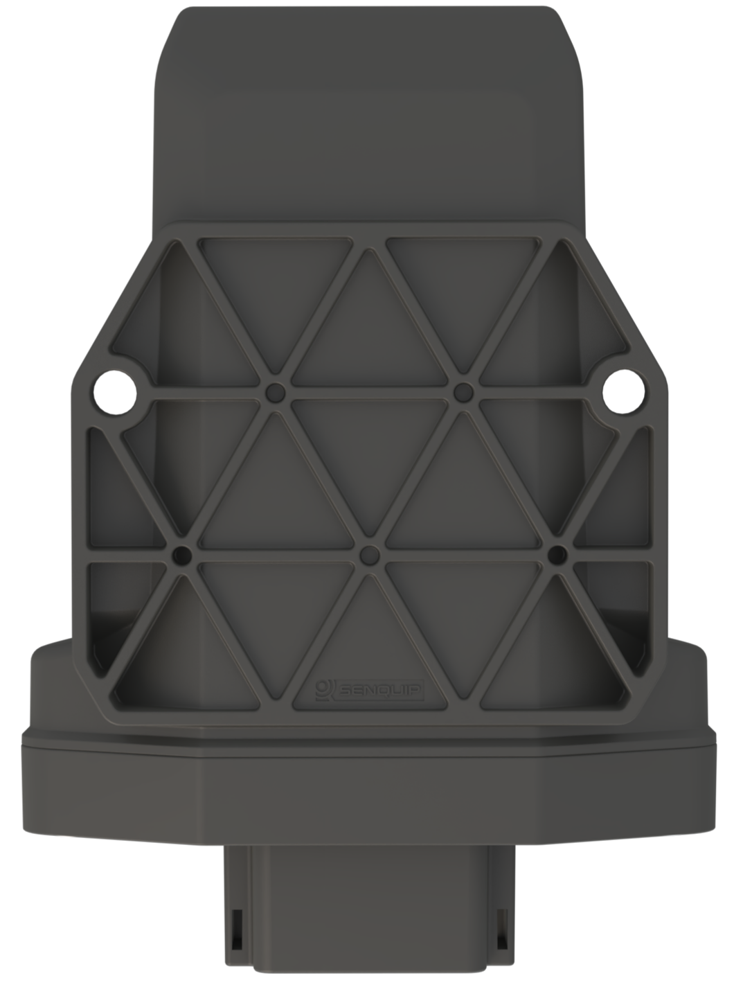
Bottom view showing UNI mounting points
For best performance, the device should be mounted such that:
Wiring is protected from damage and excessive strain.
The enclosure is not subjected to unnecessary mechanical stress.
The device is positioned away from significant sources of heat.
The connector faces downward or sideways where possible to minimise water ingress into the connector cavity during service.
Shipping Container Installation
The UNI enclosure has been designed to fit within the corrugations of a standard shipping container. When mounted within a corrugation, the device does not extend beyond the outer profile of the container, reducing the risk of accidental damage during handling and transport.

UNI mounted within a shipping container corrugation
This makes the UNI particularly suitable for container monitoring, containerised equipment, and other applications where protection from impact and snagging is important.
Note
The installer is responsible for ensuring that the mounting structure and fasteners are suitable for the application and that the installation complies with any applicable safety requirements.
User Access
The UNI is designed primarily for OEM integration and is not intended to require routine access during normal operation. Access is typically only required during commissioning to install a Nano-SIM card or perform configuration.
The enclosure is secured using two stainless steel captive screws. To access the electronics, loosen the screws and remove the enclosure from the header.
Opening the enclosure activates the internal tamper switch. Applications requiring tamper detection may use this feature to record or report unauthorised access to the device.
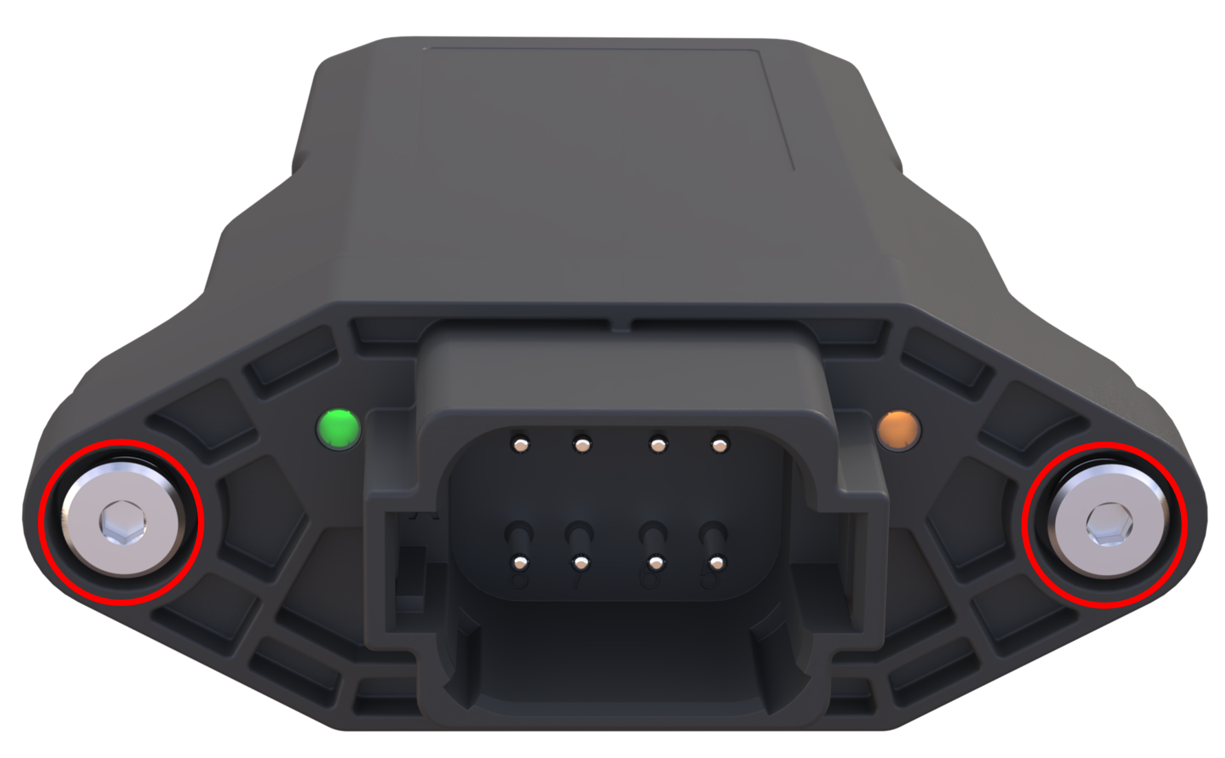
Removing the enclosure
Once the enclosure has been removed, the printed circuit board is exposed. The battery is mounted on the bottom side of the PCB, while the Nano-SIM holder, setup button, reset button, network LED, and setup LED are accessible from the top side.
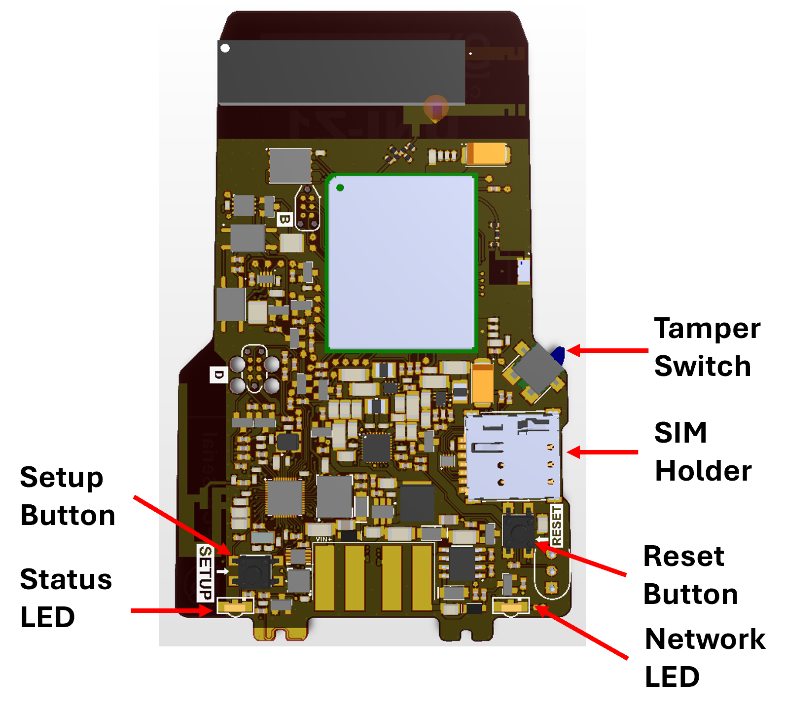
Internal components
Warning
The internal electronics may be damaged by static electricity or improper handling. Avoid touching electronic components, connector contacts, battery terminals, or exposed circuitry. Where possible, handle the PCB by its edges and observe appropriate electrostatic discharge (ESD) precautions.
Before reassembling the device, inspect the enclosure seal to ensure it is clean, correctly seated, and free from damage, dirt, moisture, or other contamination. Failure to correctly fit the seal may compromise the environmental protection of the device.
The setup button, reset button, network LED, and setup LED are described in later sections of this manual.
After any required work has been completed, ensure that the enclosure is correctly fitted to the header, the seal is correctly seated, and both captive screws are tightened before returning the device to service.
SIM Card Installation
The UNI-Z1 supports both eSIM and Nano-SIM options.
eSIM - Provision is made on the PCB for a customer-supplied MFF2 eSIM component. eSIMs provide excellent reliability in high-vibration environments. Contact Senquip for more information.
Nano-SIM - A Nano-SIM holder is provided for customers wishing to use their own SIM cards. Nano-SIMs offer the greatest flexibility and network choice.
If mobile communications are required and an eSIM is not fitted, a Nano-SIM card must be installed. The UNI-Z1 supports both 1.8V and 3.3V Nano-SIM cards.
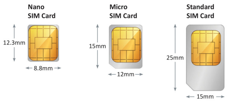
SIM card sizes
Note
If your UNI-Z1 is fitted with an eSIM, a Nano-SIM card is not required.
To access the Nano-SIM holder, remove the enclosure from the header as described in the User Access section.
The SIM holder is a push-push type. To install a Nano-SIM card, push it fully into the holder until it clicks into place. To remove the SIM card, push it gently and release. The SIM card will eject from the holder.
With the PCB viewed from the SIM holder side and the Deutsch connector closest to you, insert the Nano-SIM card with the contacts facing down and the chamfered corner in the lower-left position, as shown below.
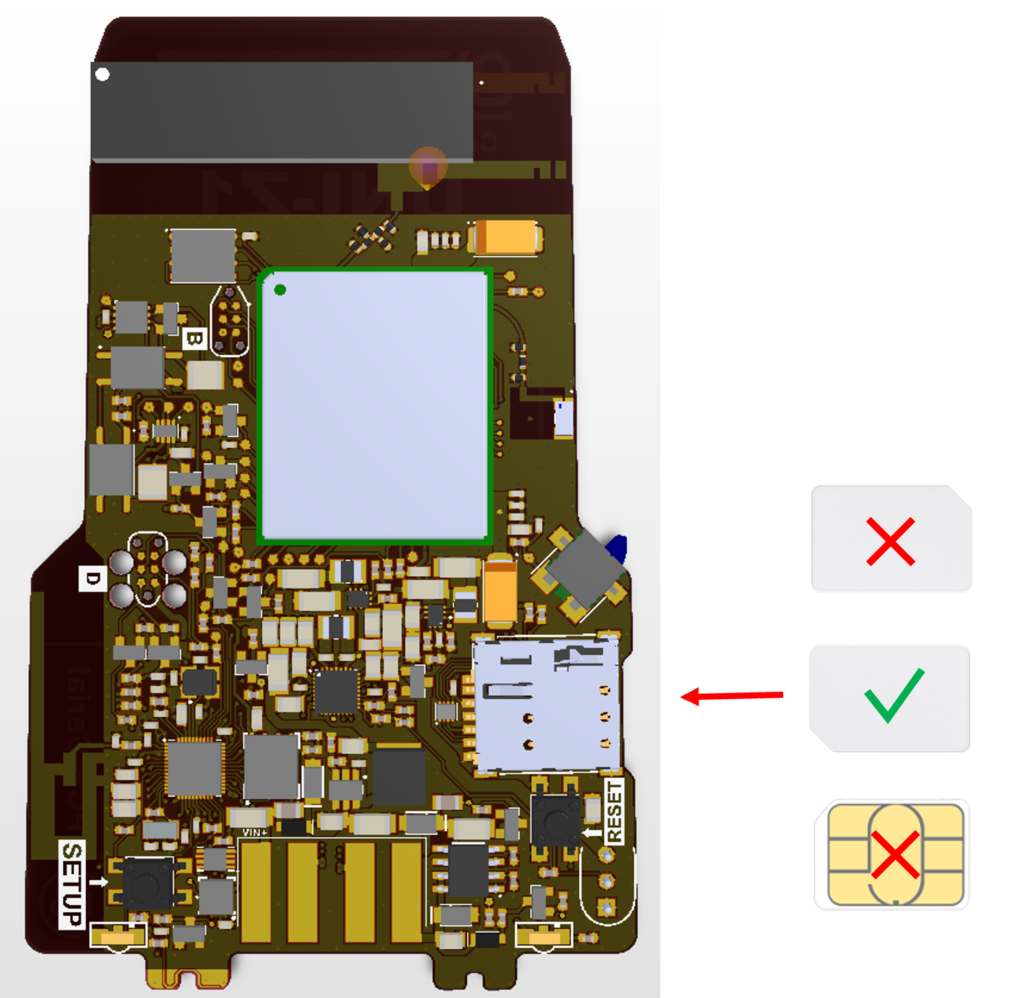
Correct orientation of a Nano-SIM card
The enclosure incorporates a retention feature that secures the SIM card when the enclosure is fitted to the header. Ensure that the enclosure is fully seated and both captive screws are tightened after installing the SIM card.
After installing or removing a SIM card, it is recommended that the UNI-Z1 be reset so that the modem can detect the change.
Wiring Guide
The Senquip UNI-Z1 uses an integrated 8-way Deutsch DT connector to provide power and communications interfaces. Looking into the mating face of the connector, pin 1 is in the upper-left corner and numbering proceeds clockwise.
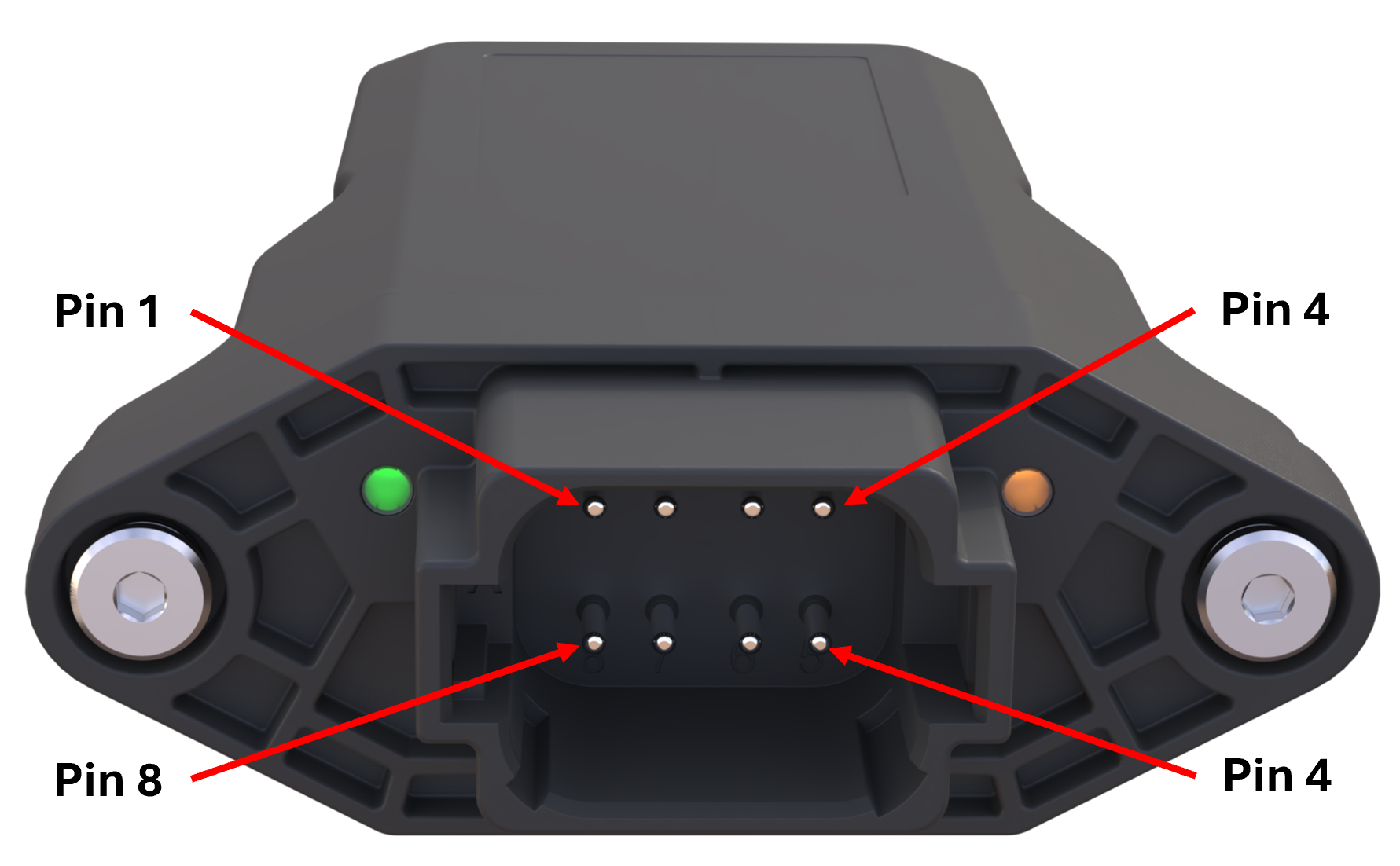
Connector pin numbering
The following pinout applies to the connector:
Pin Number |
Signal |
Application |
|---|---|---|
1 |
VIN |
Positive supply voltage |
2 |
RS485 B |
RS485 B |
3 |
CAN1 L |
CAN bus 1 low |
4 |
IO1 |
General purpose input/output 1 |
5 |
IO2 |
General purpose input/output 2 |
6 |
CAN1 H |
CAN bus 1 high |
7 |
RS485 A |
RS485 A |
8 |
GND |
Ground |
The mating connector is not supplied with the device and must be purchased separately.
Component |
Part Number |
|---|---|
Plug Housing (A Key) |
DT06-08SA |
Wedge Lock |
W8S |
Socket Contacts |
0462-201-16141 |
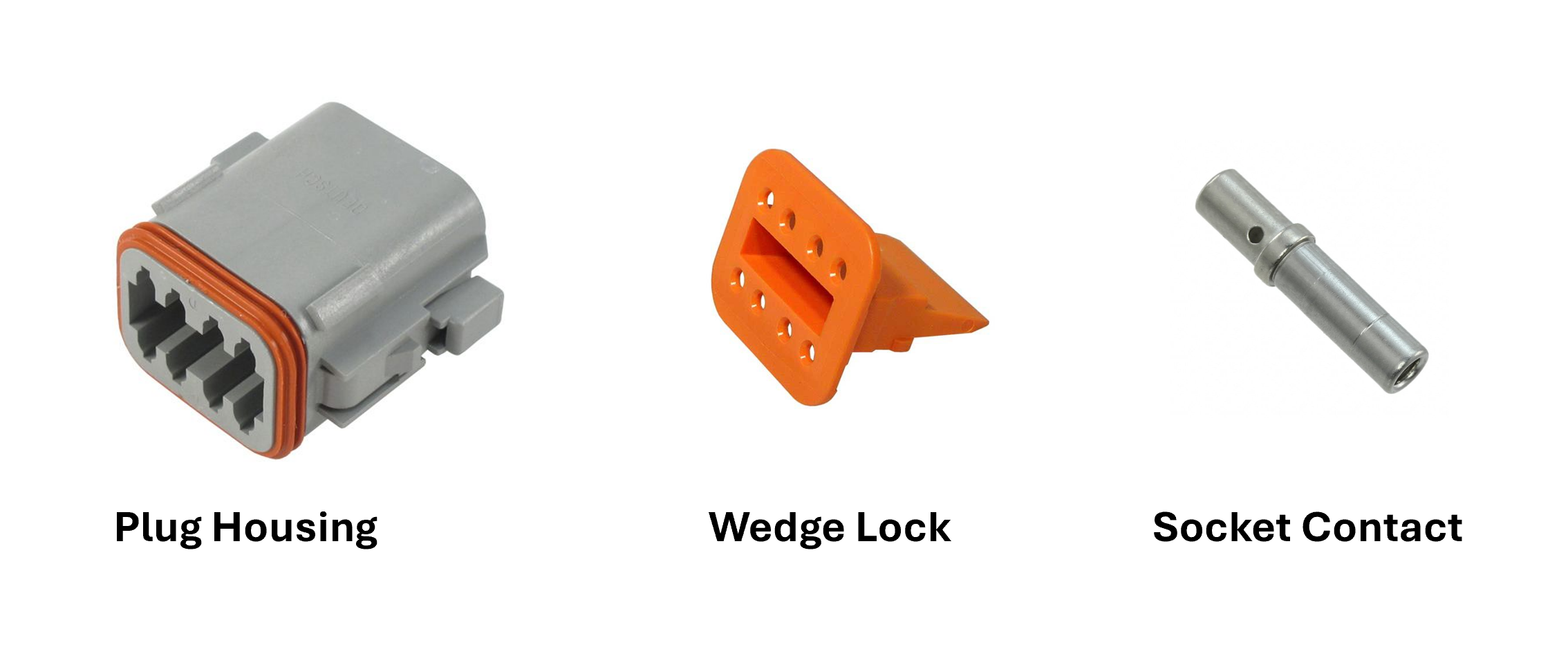
Deutsch connector parts
Note
Deutsch connectors are keyed - be sure to order the A Key plug housing
The recommended wire size for the 0462-201-16141 socket contacts is 0.5mm^2 to 2.0mm^2 (20 to 14 AWG).
The Deutsch contacts must be crimped using an appropriate Deutsch-compatible crimp tool. Improper crimping can result in increased contact resistance, intermittent operation, or reduced environmental sealing. After crimping, lightly pull each wire to verify correct contact retention before inserting the contact into the connector housing.
To maintain the environmental sealing of the connector:
Ensure all populated cavities contain correctly installed contacts.
Ensure the wedge lock is fitted after assembly.
Ensure the connector is fully mated and latched.
Fit suitable cavity plugs to any unused cavities if environmental sealing is required.
Warning
Ensure that all external power is removed from the device before wiring fitment begins.
Power and ground wires must be rated to at least 1A and should have a voltage rating suitable for the application. A 1A fuse in-line with the power connection is recommended.
Signal wires should be chosen based on the application and may require specific features such as individual shielding, twisted pairs, or impedance matching. In extremely noisy electrical environments, it is recommended that a shielded cable be used and that the shield only be connected to ground at the power supply end. Do not ground the shield at both ends.
The material from which the chosen cable is manufactured should be suitable for the environment in which it is used. Check chemical resistance, UV stability, and flex durability of the cable being used.

Typical wiring arrangement
Initial Setup
Initial setup can be performed using the integrated web-server using any Wi-Fi enabled phone, tablet or computer or with the Senquip connect App with an Android or iOS device. Once the device is connected to a network, it is recommended that configuration be continued using the Senquip Portal.
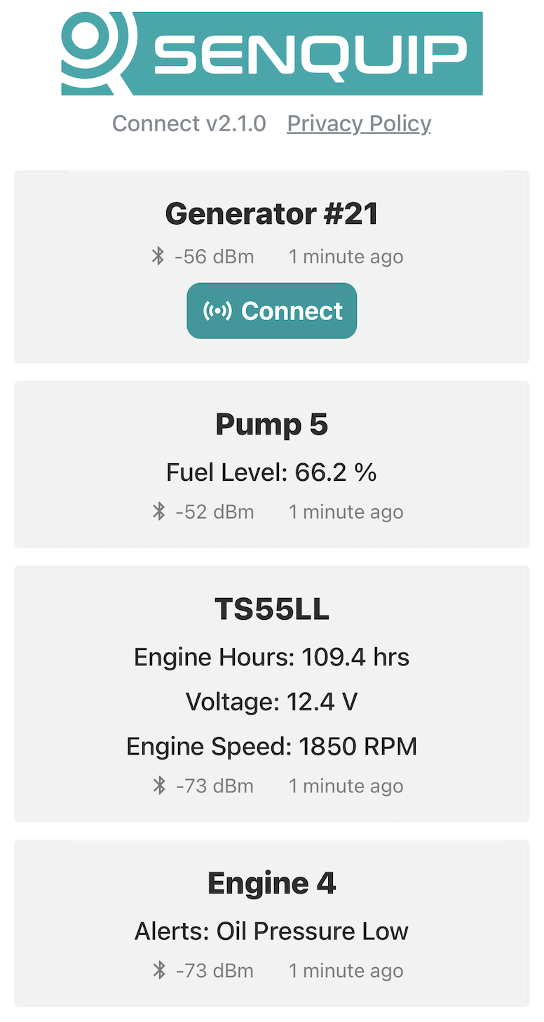
Senquip Connect App
Note
For volume opportunities, devices can be pre-configured to connect immediately to a network; please contact Senquip to discuss this option.
With the cover open, two push-button switches (setup and reset) and two LEDs (network and status) are available. The switches and LEDs are used to configure the device.
LED Indicators
The UNI provides two LED indicators that are visible externally through light pipes integrated into the header.
Status LED (Green) - Located to the left of the Deutsch connector.
Network LED (Orange) - Located to the right of the Deutsch connector.
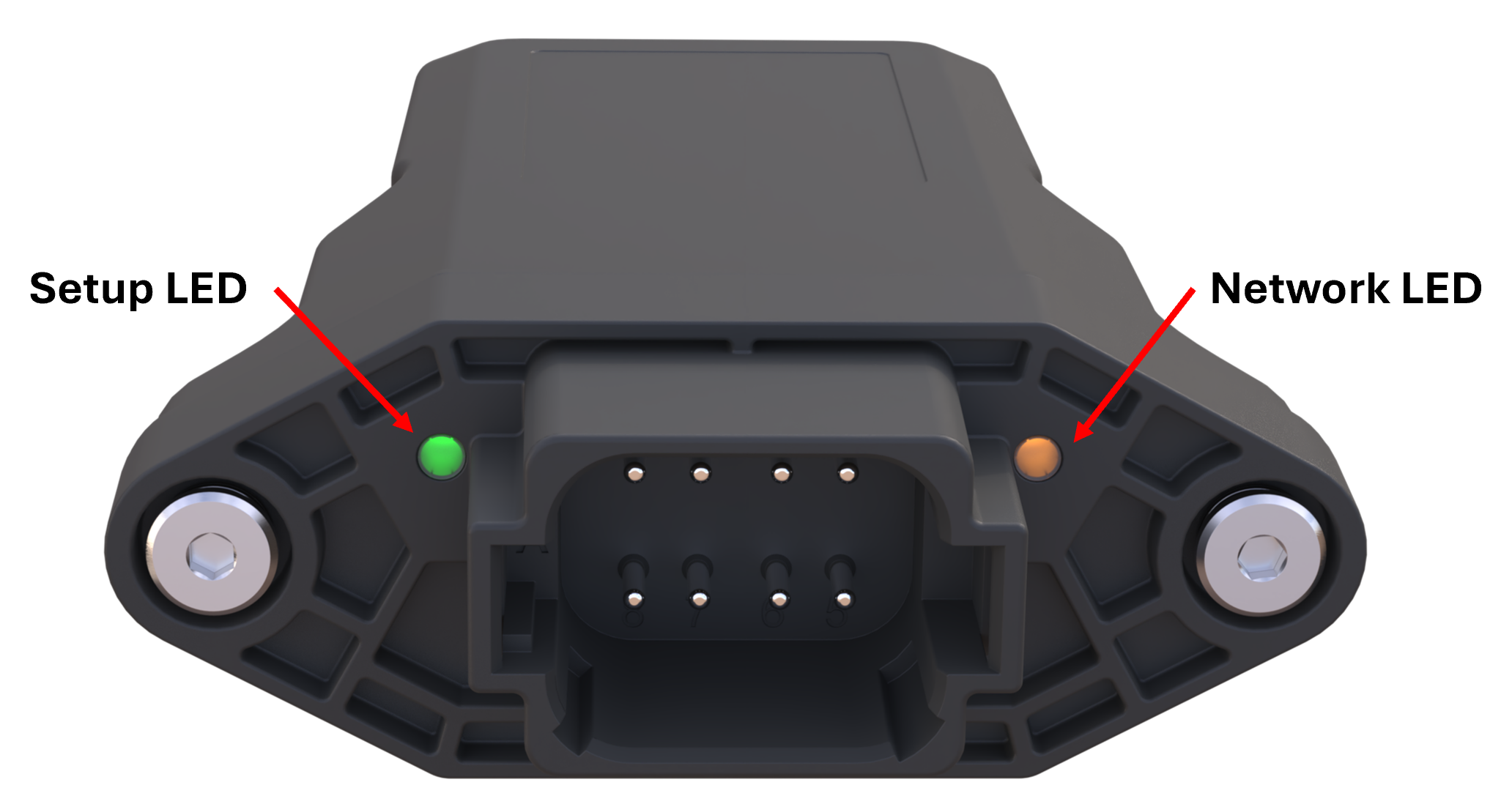
UNI LED locations
The LEDs are enabled by default and provide information about device status, configuration mode, and network connectivity. If required, the LEDs may be disabled through the device settings.
When the enclosure is removed from the header, the internal tamper switch is activated and the LEDs will illuminate regardless of the LED enable setting. This allows commissioning, diagnostics, and servicing to be performed even when the LEDs are disabled during normal operation.
The LED flash patterns are identical to those used by the ORB and QUAD products and are described in the tables below.
Status LED |
Network LED |
Meaning |
|---|---|---|
(Green) |
(Orange) |
|
Off |
Off |
Device is sleeping or lid is closed |
Flash (1Hz) |
Off |
Setup Mode |
On |
Flash (1Hz) |
Searching for network |
On |
Pulse off (2 sec) |
Attached to network (Wi-Fi or LTE), but not connected to Senquip Portal |
On |
On |
Attached to network and connected to Senquip Portal |
Fast Flash |
Fast Flash |
Factory reset in progress |
Off |
Fast Flash |
Firmware update in progress |
Slow Flash |
Off |
Pre-charge mode |
Firmware Updates
The latest firmware version and a description of changes to firmware can be found in the Senquip Device Firmware Changelist.
Updating to the latest firmware can be performed from the Senquip Portal by selecting Settings and Update and then pressing the Update Firmware button. To update to a specific firmware version, enter the exact firmware number and press Update Firmware. During the firmware update, the orange network LED will flash fast. After a firmware update, the LEDs may freeze or remain off for a few minutes. This is normal behaviour and occurs shortly after firmware update when the UNI-Z1 is encrypting the memory.
The firmware update can be seen in the command queue and has been received by the device when the status shows as success. Receipt of the firmware update by the device does not always mean that the update is correctly applied. To ensure that the update has occured, check the firmware number in the Device Info widget on the device Portal page. You may need to refresh the browser window.
Factory Reset
To perform a factory reset, press and hold the Setup button. While holding the Setup button, press and release the Reset button. The green status LED and orange network LED will begin to flash fast. Continue to hold the Setup button down for 10 seconds. After 10 seconds, the LEDs will stop flashing at which point the Setup button can be released. All settings will be changed back to the factory state and the device will restart. Any firmware updates made to the device will be preserved.
Warning
Returning the device to factory defaults will remove all network settings, rendering remote updates impossible.
Passwords
Each UNI-Z1 is supplied with unique factory-generated credentials that protect access to the device and simplify commissioning.
The credentials are generated using a cryptographically secure random number generation process and are unique to each device.
The device is supplied with a credentials card located inside the enclosure containing:
Device ID
Setup Password (SETUP PASS)
Wi-Fi Access Point Password (WIFI PASS)
Quick Add QR code
Quick Start Guide QR code
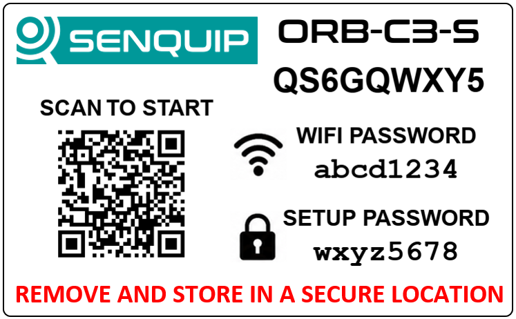
Device credentials card
The Device ID uniquely identifies the device within the Senquip Portal.
The Setup Password is used to access device settings through the Senquip Connect App or device webserver while the device is in setup mode. The Setup Password may also be used to establish administrative access to a device if no administrator has yet been assigned.
The Wi-Fi Password protects access to the device’s Wi-Fi Access Point when local wireless configuration is required.
The Quick Add QR code contains the Device ID and Setup Password, allowing an authenticated Senquip Portal user to add the device to their account with a single scan.
The Quick Start Guide QR code links to the latest installation and commissioning instructions for the device.
Warning
Store the credentials card in a secure location. Anyone with access to the Device ID and Setup Password may be able to establish administrative access to the device.
Password Management
Authorised administrators may change the Setup Password and Wi-Fi Password through the Senquip Portal.
If a password is forgotten, an administrator may retrieve the current password through the Senquip Portal following identity verification.
Factory Reset
A factory reset restores device settings to their factory defaults, including the factory default passwords.
A factory reset does not change device ownership, user permissions, or the device identity recorded by the Senquip Cloud.
Administrative Recovery
If all administrator accounts are inadvertently removed from a device, administrative access may be re-established using the Setup Password.
Where appropriate verification can be completed, Senquip may also assist in restoring the original administrator account associated with the device.
Setup Mode
Setup Mode enables local configuration of the UNI-Z1 using either the Senquip Connect App via Bluetooth or the device’s embedded web server via Wi-Fi.
Entering Setup Mode
To enter Setup Mode, power the UNI-Z1 and wait for the green Status LED to become solid. Press the Setup button. When the green Status LED starts flashing, the device is in Setup Mode.
If connected to external power, the UNI-Z1 will remain in Setup Mode while the lid is open. If external power is not available, the UNI-Z1 will enter sleep mode after 10 minutes of inactivity. To re-enter Setup Mode, press the Setup button again for 2 seconds.
Setup Mode is exited once the lid has been closed for more than 10 seconds.
Configuring the Device
Once the UNI-Z1 is in Setup Mode, local configuration can be performed using either:
Senquip Connect App (recommended) - connects to the UNI-Z1 via Bluetooth.
Embedded Web Server - connects to the UNI-Z1 via its Wi-Fi access point using a web browser.
For detailed instructions on using either method, see First Connection.
Note
Once a network connection has been established, it is recommended that further device configuration be performed remotely using the Senquip Portal.